
After 5 months of research and coding, my 2008 M3 CCC-based iDrive have been replaced by the 2009-on CIC-based iDrive:
December 2009: New CIC (no programming at all yet), HD Screen cable, controller and console, used HD Screen and USB cable installed:
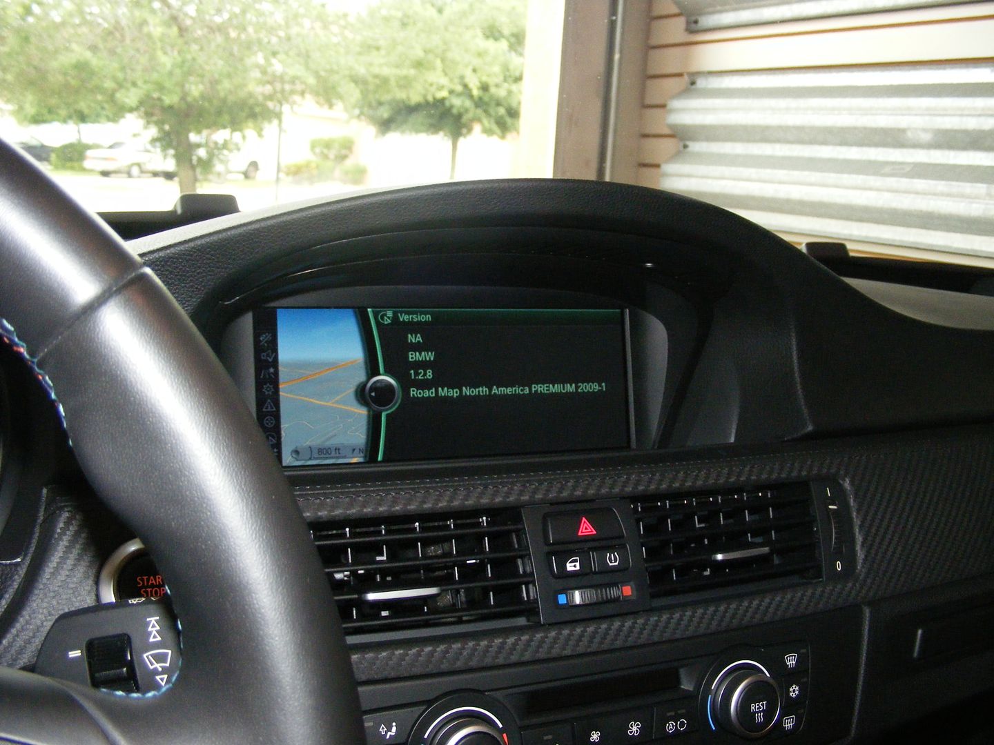
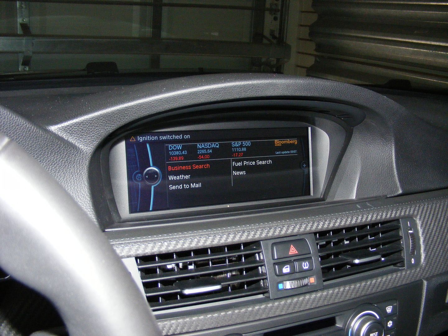
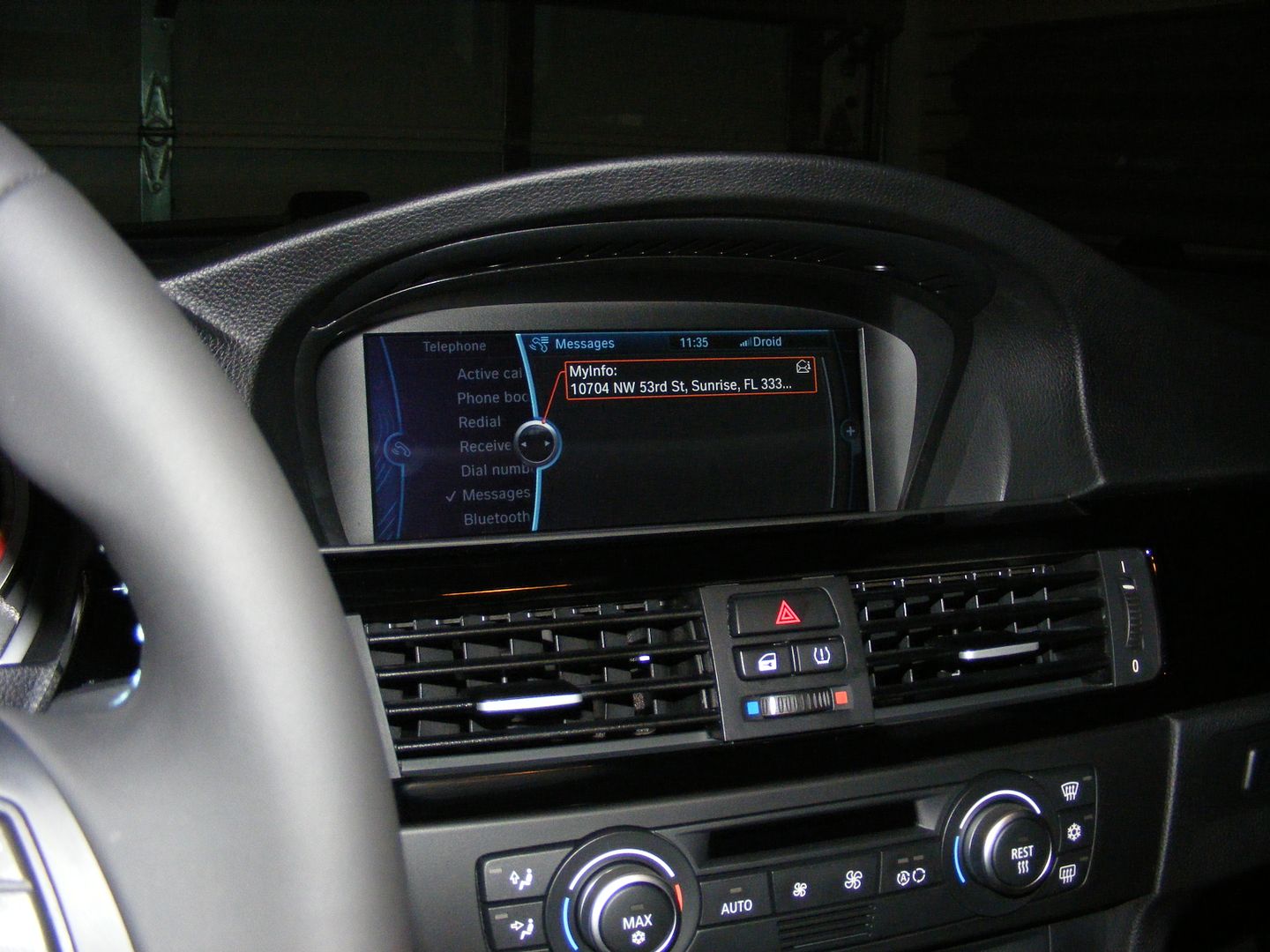
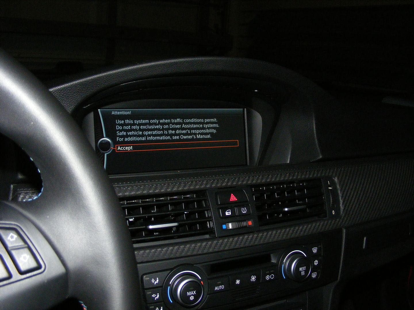
Legal screenshot...
![Image]()
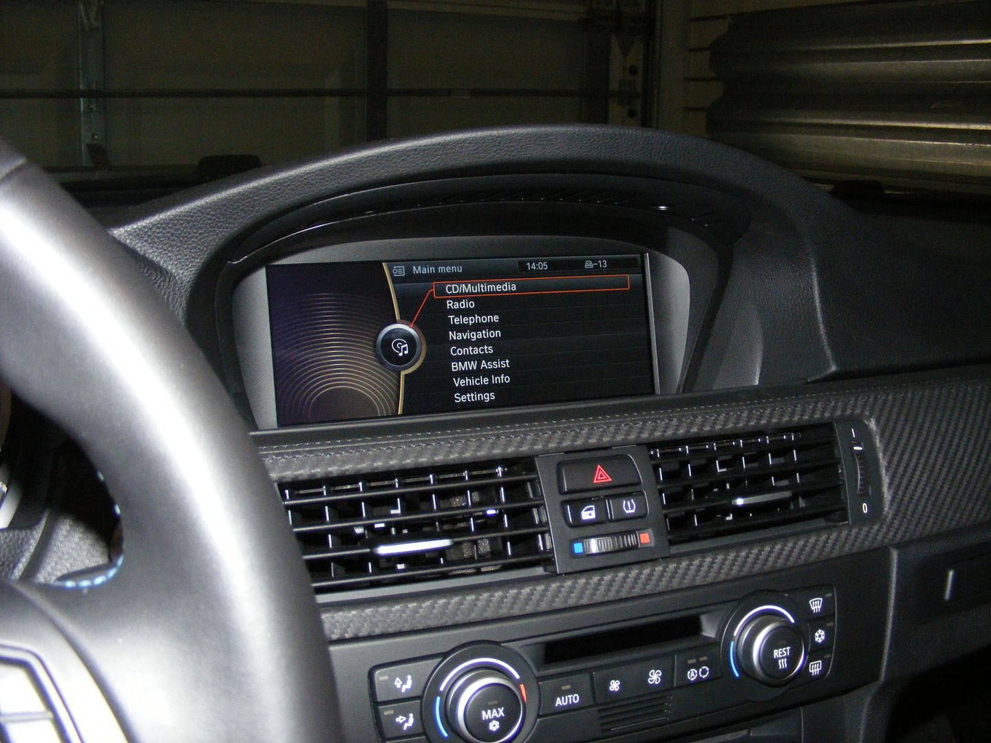
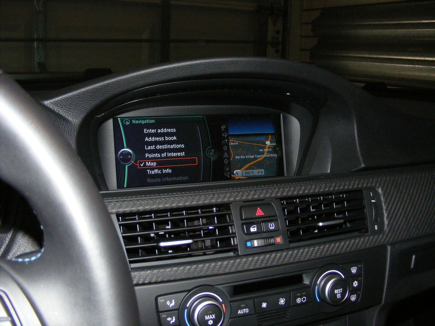
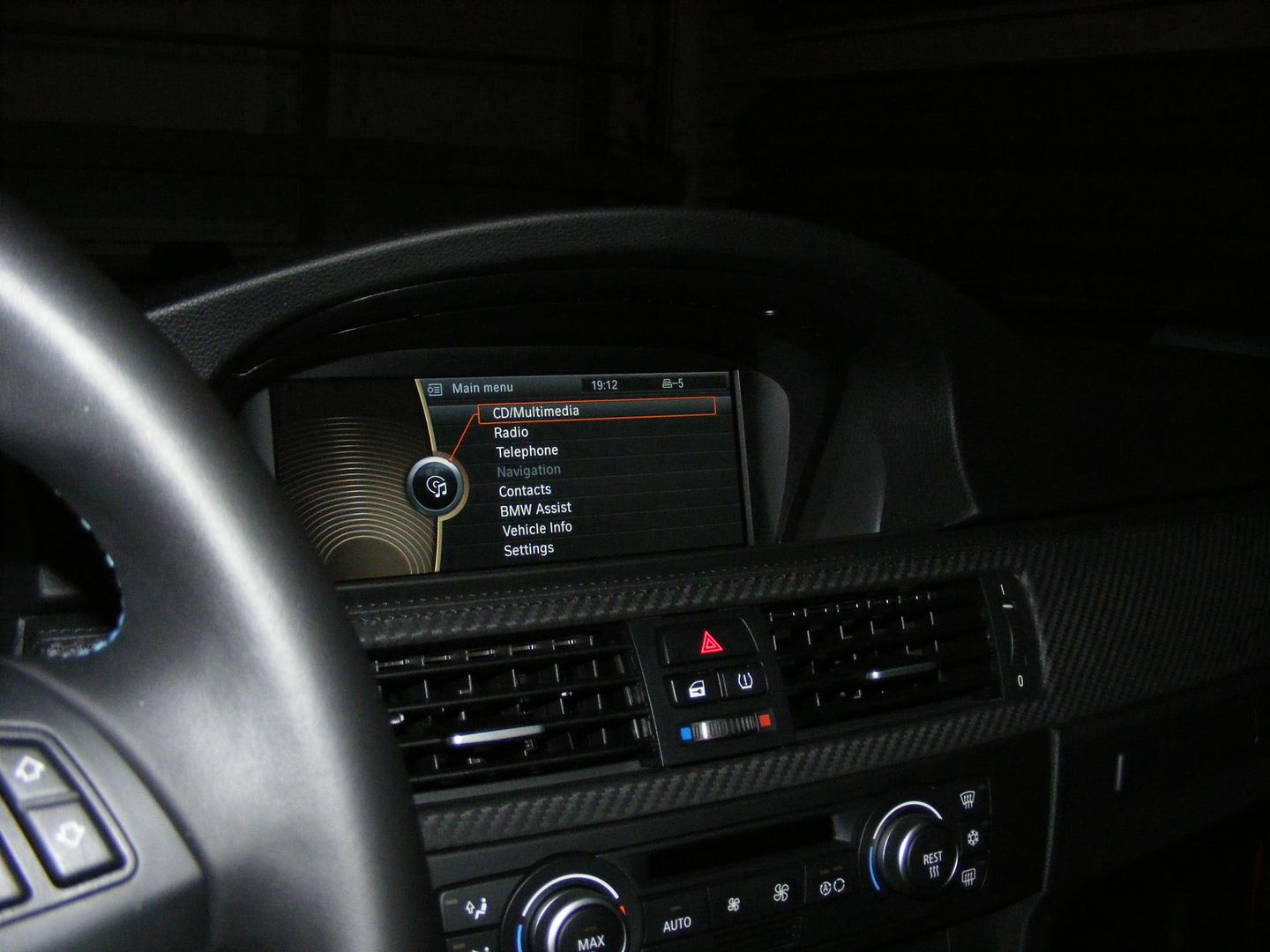
Main menu (Navigation grayed out as it is not enabled)...
![Image]()
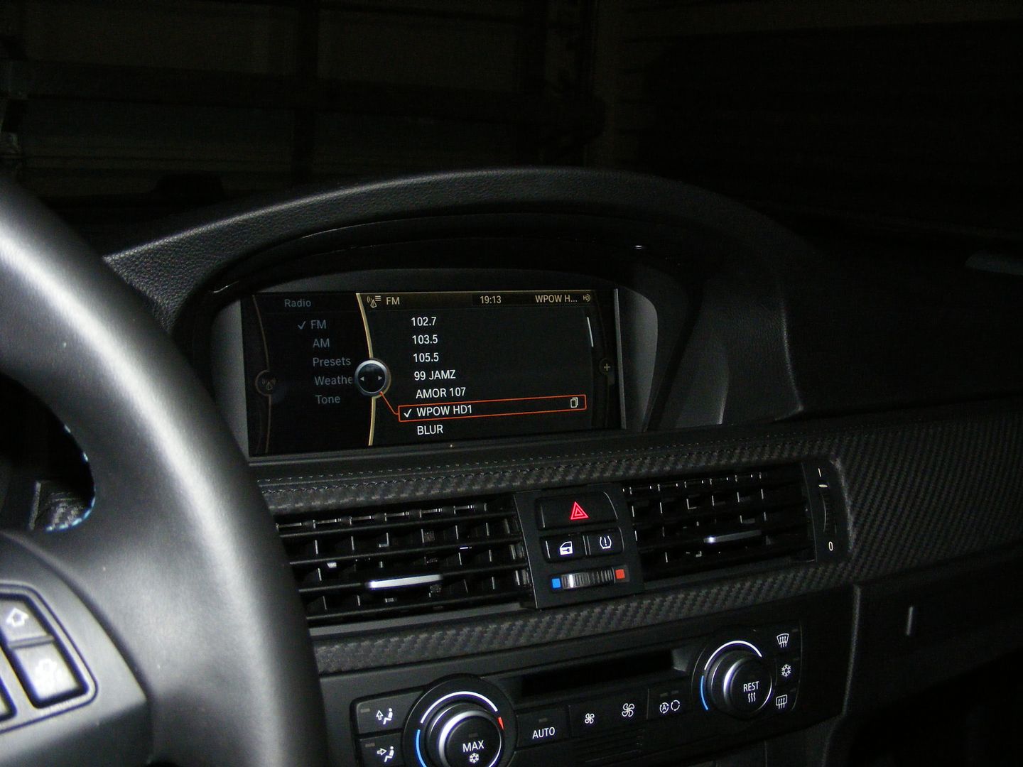
HD Radio...
![Image]()
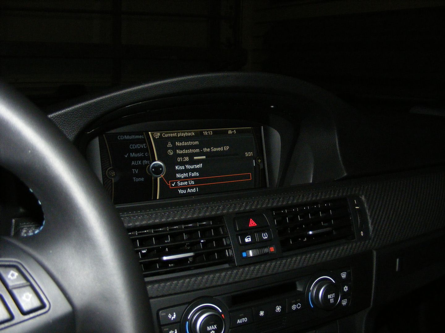
HDD with 30+ MP3 songs already downloaded (320kps) thru the USB port...
![Image]()
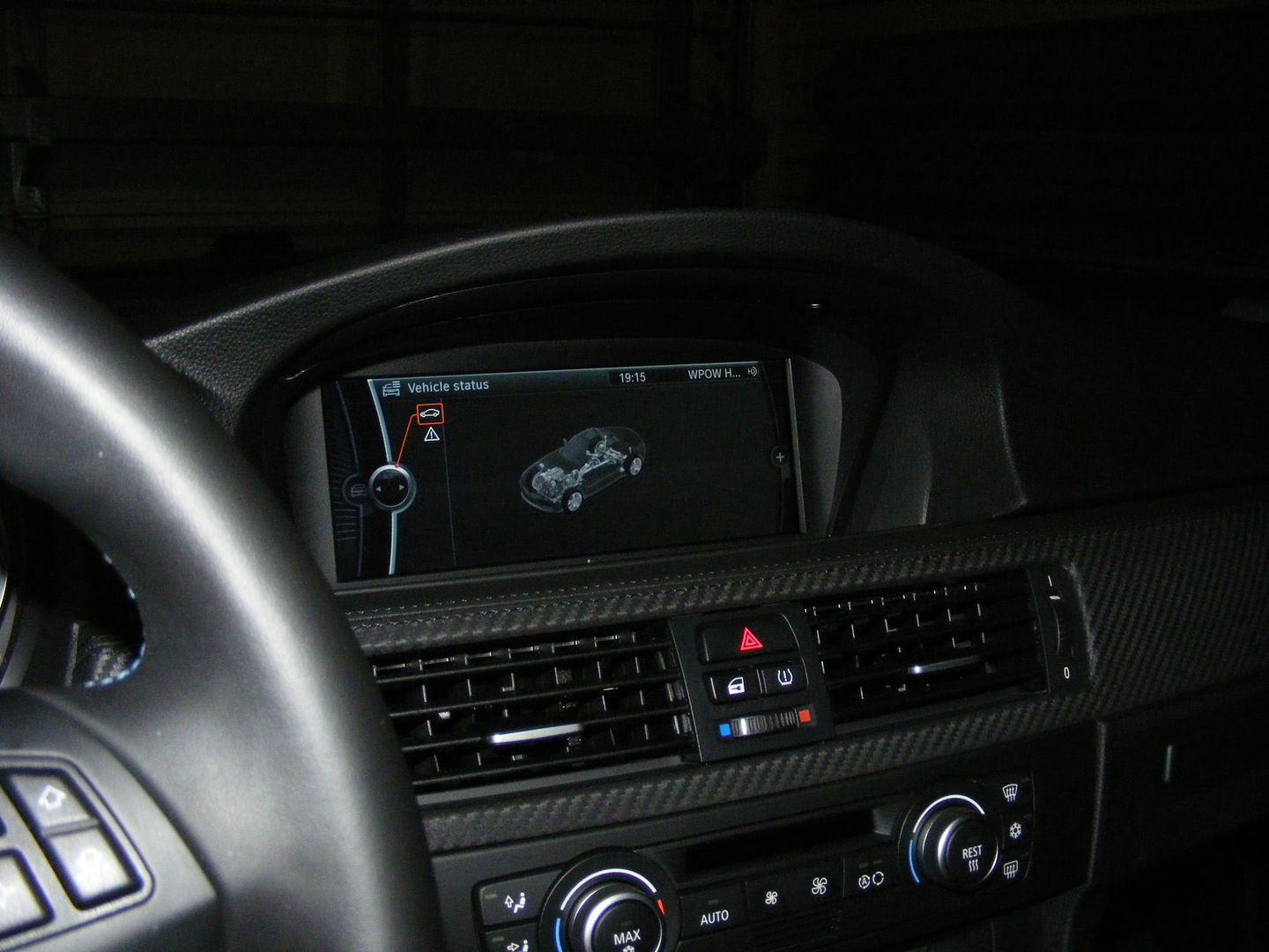
Vehicle status (note that the vehicle shown is a Z4, once the CIC is properly programmed an E90 M3 will be shown)...
![Image]()
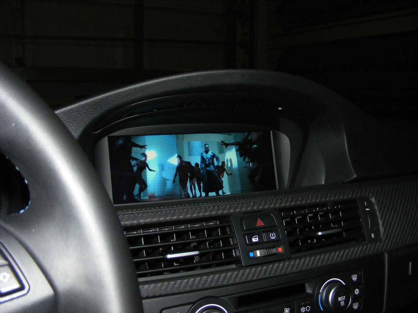
DVD -screw Twilight... bring fricking Blade to kill some suckers!!
![Image]()
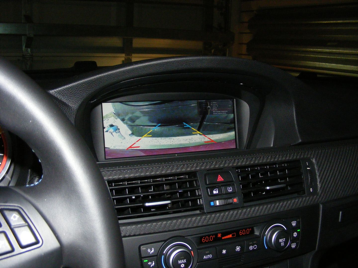
MentholGuy's reverse camera for 2009 iDrive...
![Image]()
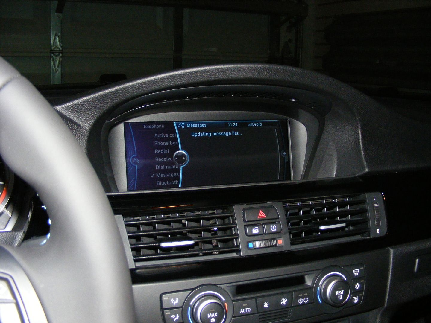
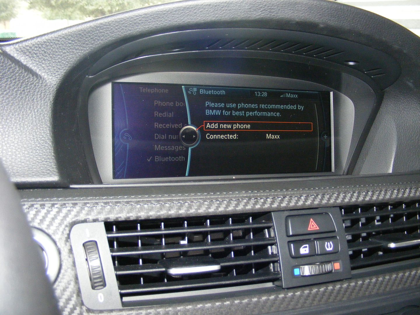
Assist/Bluetooth fully functional:
![Image]()
Notes for installation:
- CIC plugs right into the CCC Quadralock connector, Radio and GPS antenna.
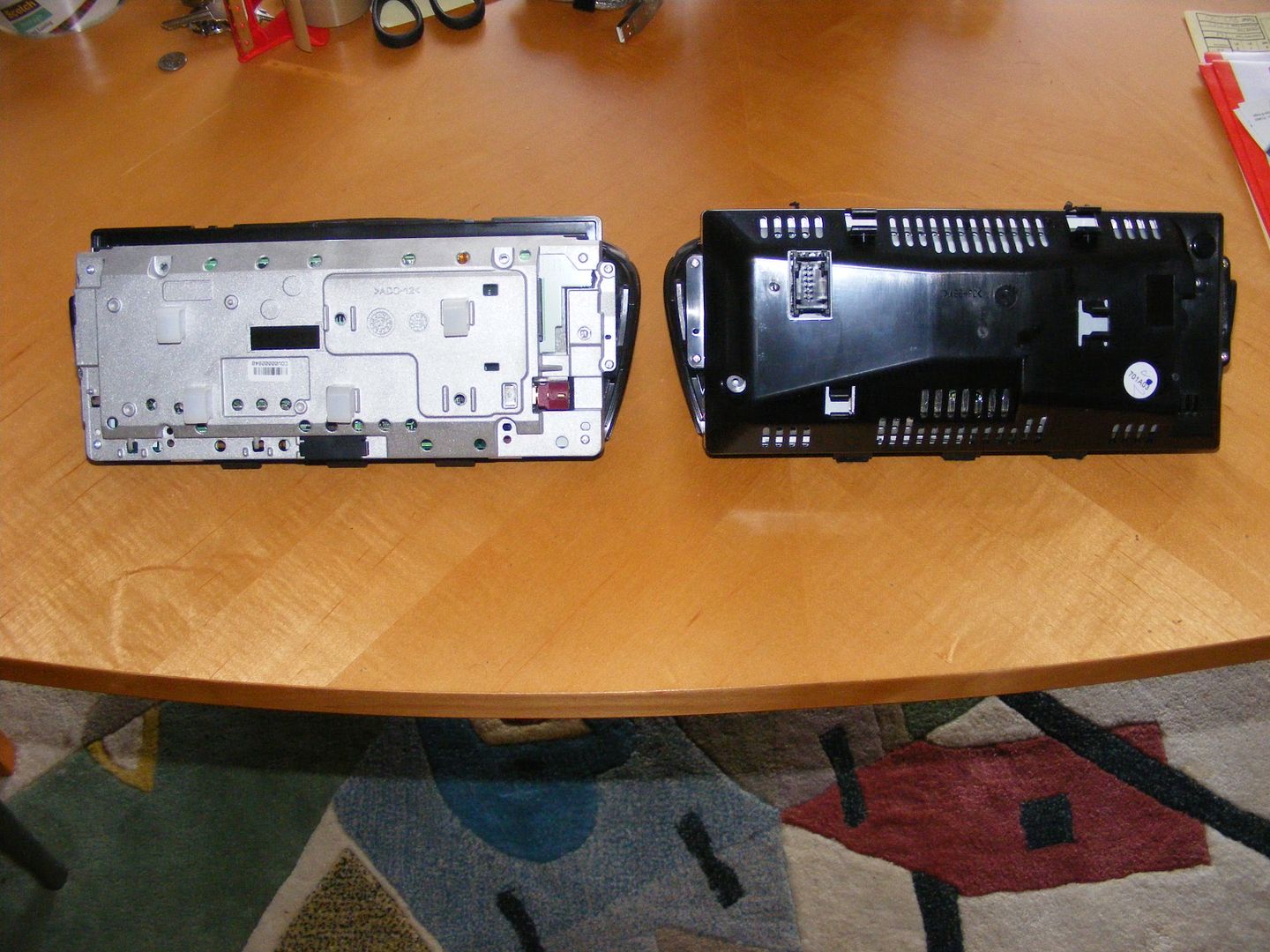
- HD Screen installs -and uses same screws- in the dash as non-HD Screen. HD Screen requires new video cable and new Power/CAN connector, though:
HD Screen (CIC) on the left, non-HD Screen (CCC) on the right:
![Image]()
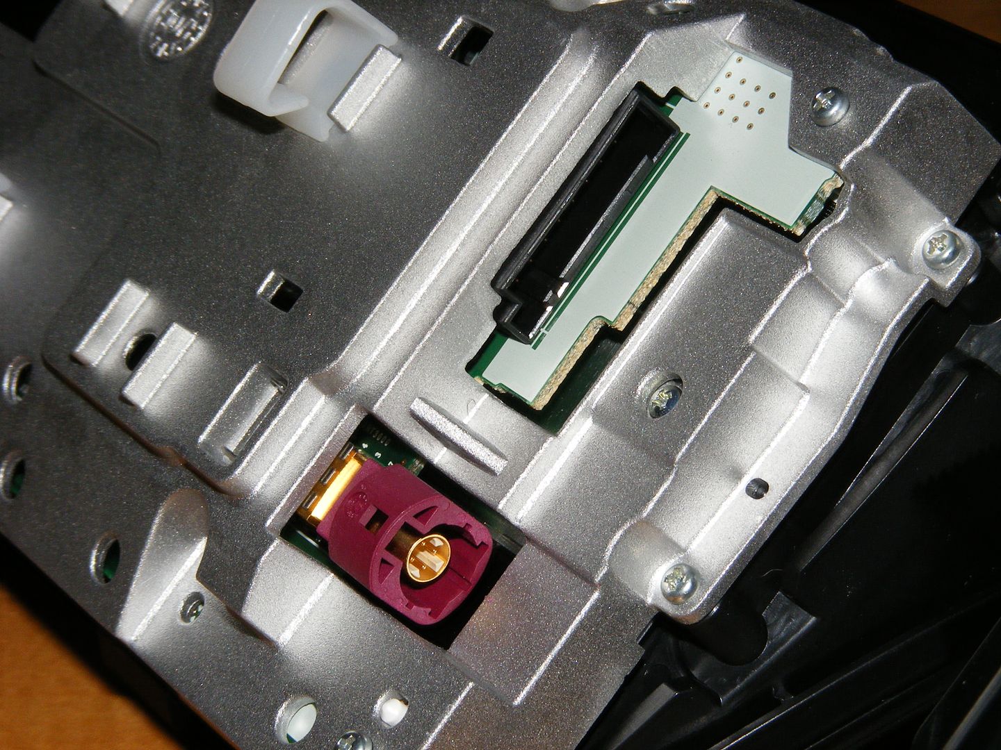
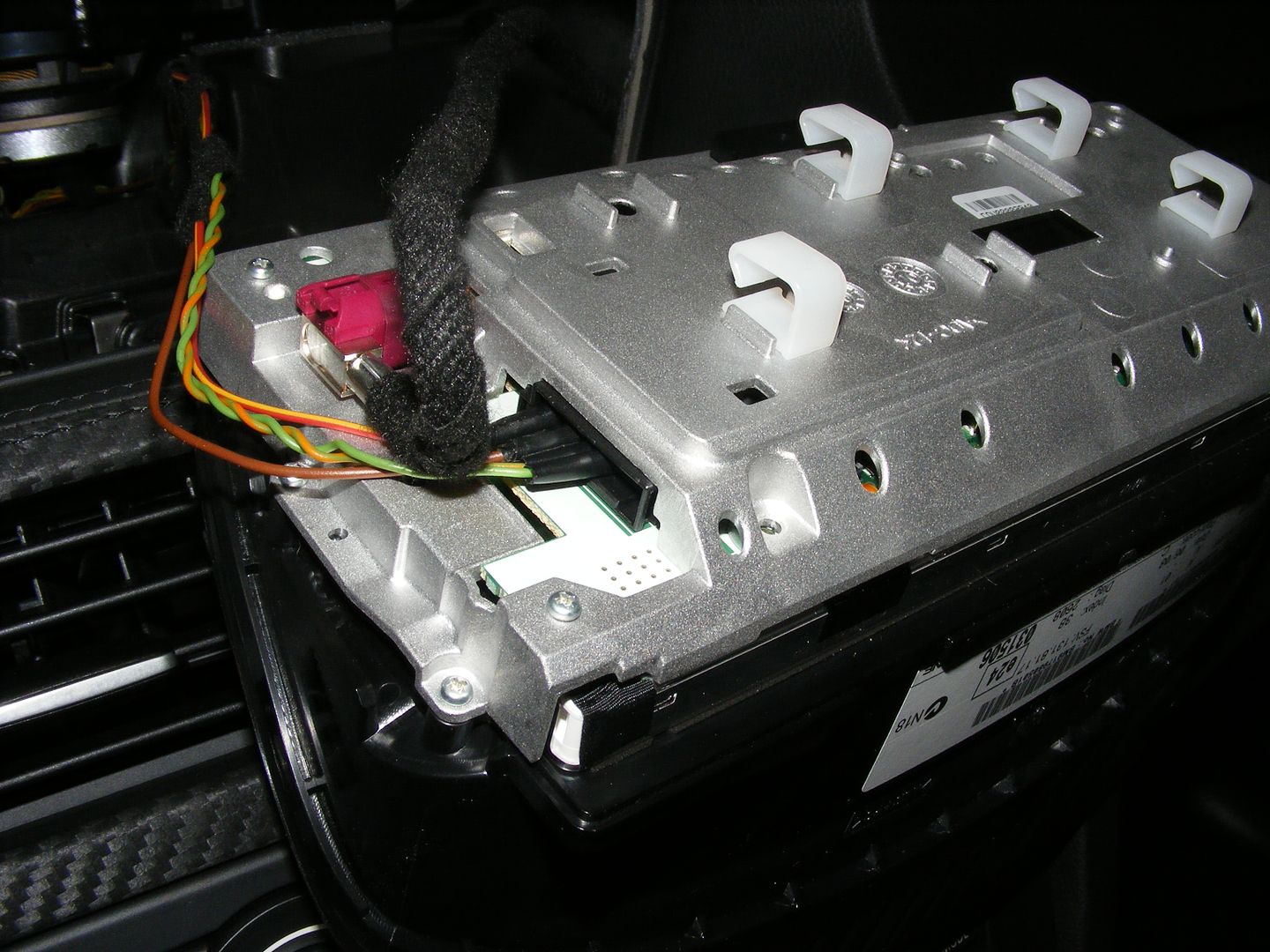
HD Screen video cable jack (round, 4 wires), Power/CAN jack (rectangular, pins #1-8 in a single row):
![Image]()
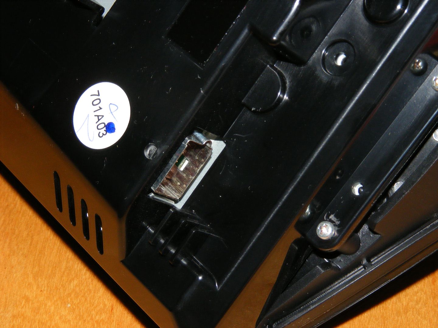
non-HD Screen video cable jack (rectangular, 8-wires):
![Image]()
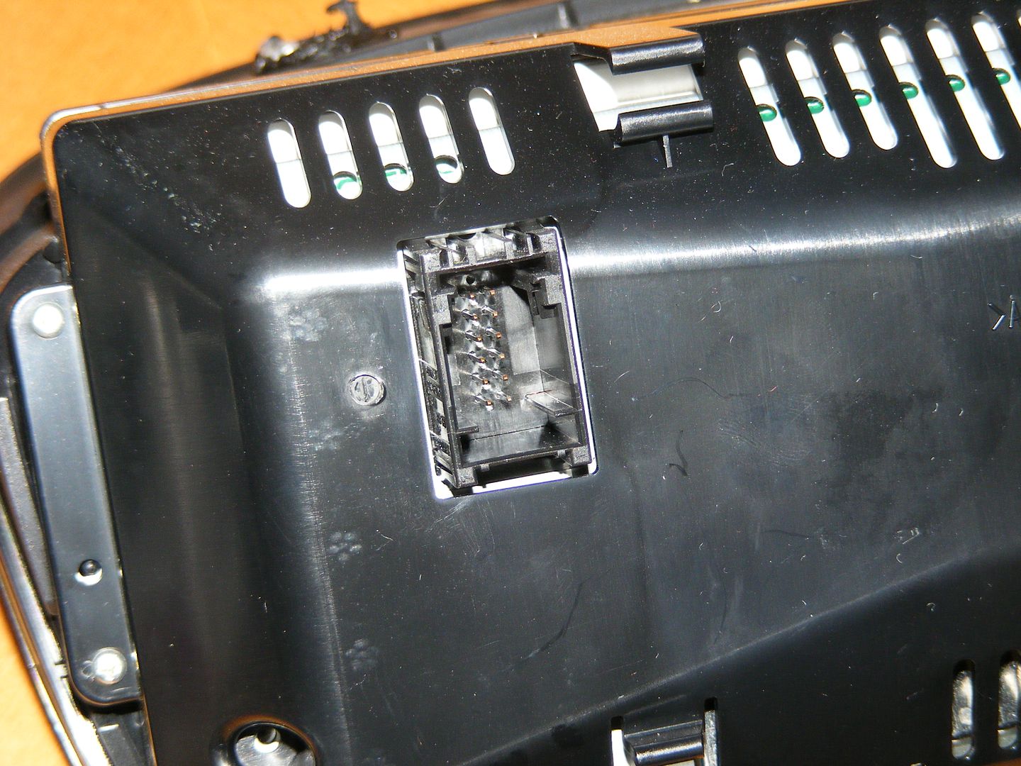
non-HD Screen Power/CAN jack (rectangular, pins #1-12 in double rows):
![Image]()
The good news is that the Power/CAN wires (4 wires total) are exactly the same between the two different connectors, and they are located in exactly the same pin slots in both connectors (1, 3, 5 and 6).
The slot numbers are molded in the connectors and inside the connector jack (with the male pins) on each screen.
So it is a matter of getting the new connector with the used HD Screen (if possible) and removing the wires on by one from the existing double row connector and inserting each wire in exactly the respective slot in the new single row connector -wire in slot #1 from double row goes in slot #1 in single row connector, and so on.
Old, double row connector:
![Image]()
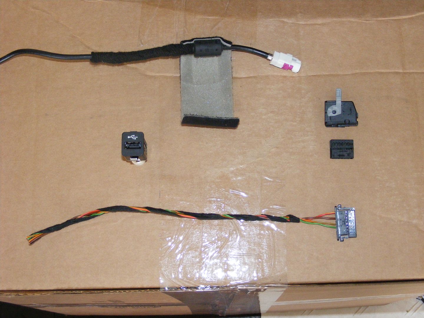
New, single row connector (bottom of photo, with USB port, USB cable and old double row connector with locking sleeve):
![Image]()
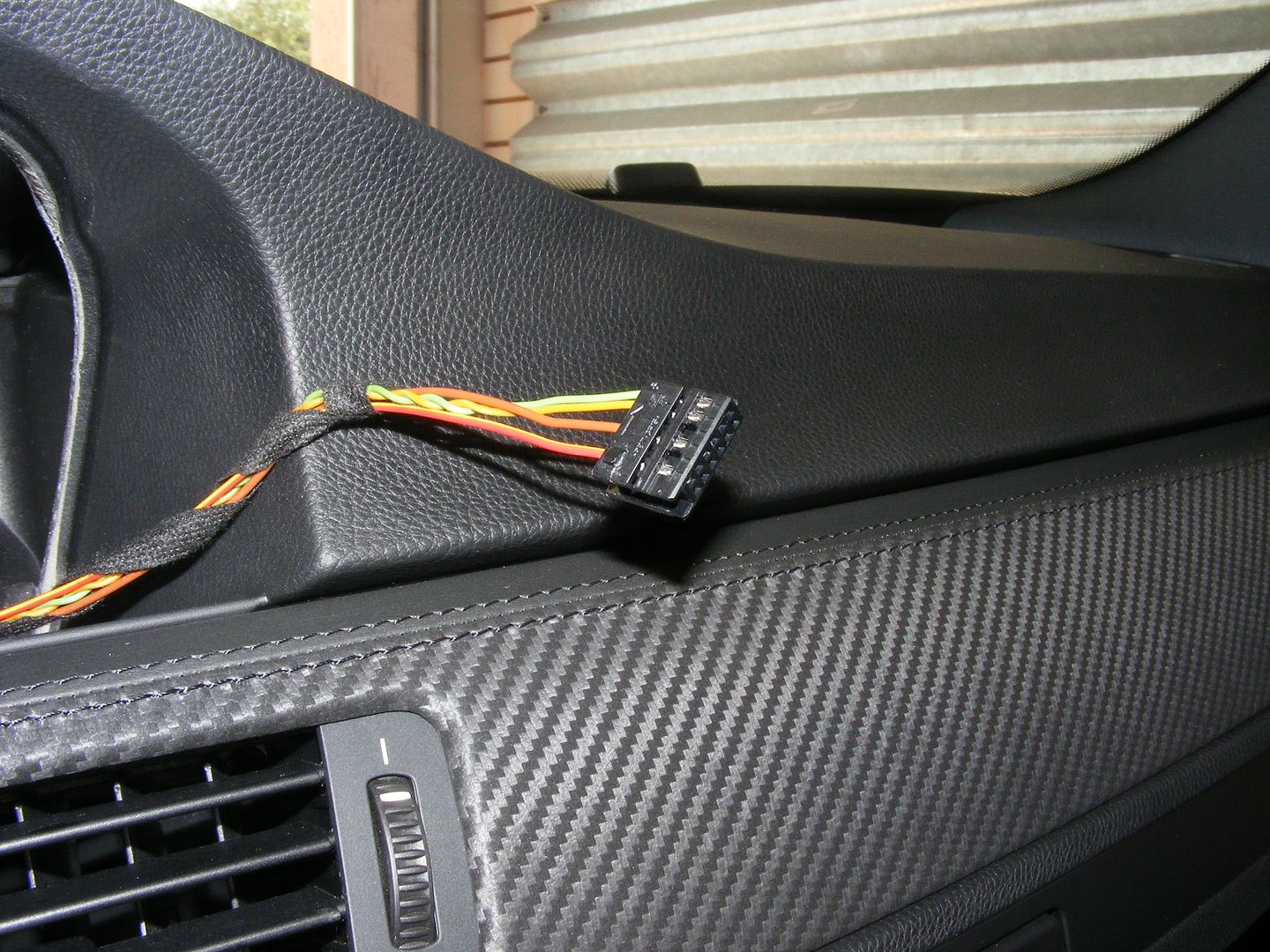
If you cannot get that single row connector with your used HD Screen (most junkers sell the HD Screen with the connector and the wires cut) then a ****ty solution -until you can get the proper connector, no P/N is available yet- could be either wrapping each pin with electrical tape or with shrink tubing and just plug each female jack into their respective male pins of the HD Screen (again, 1 to 1, 3 to 3, 5 to 5, and 6 to 6):
![Image]()
The elusive USB cable (no P/N is available so far):
![Image]()
The video cable looks exactly the same as the USB cable but without that built-in circuitry/filter bump shown with the velcro wrapper above.
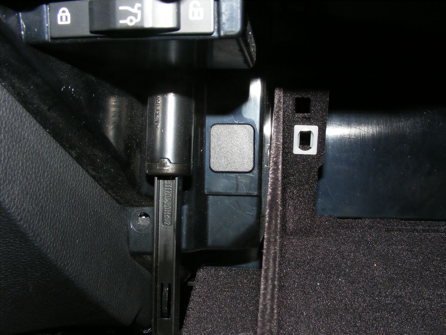
USB mount in glovebox is already made, just covered with a plastic plug...
![Image]()
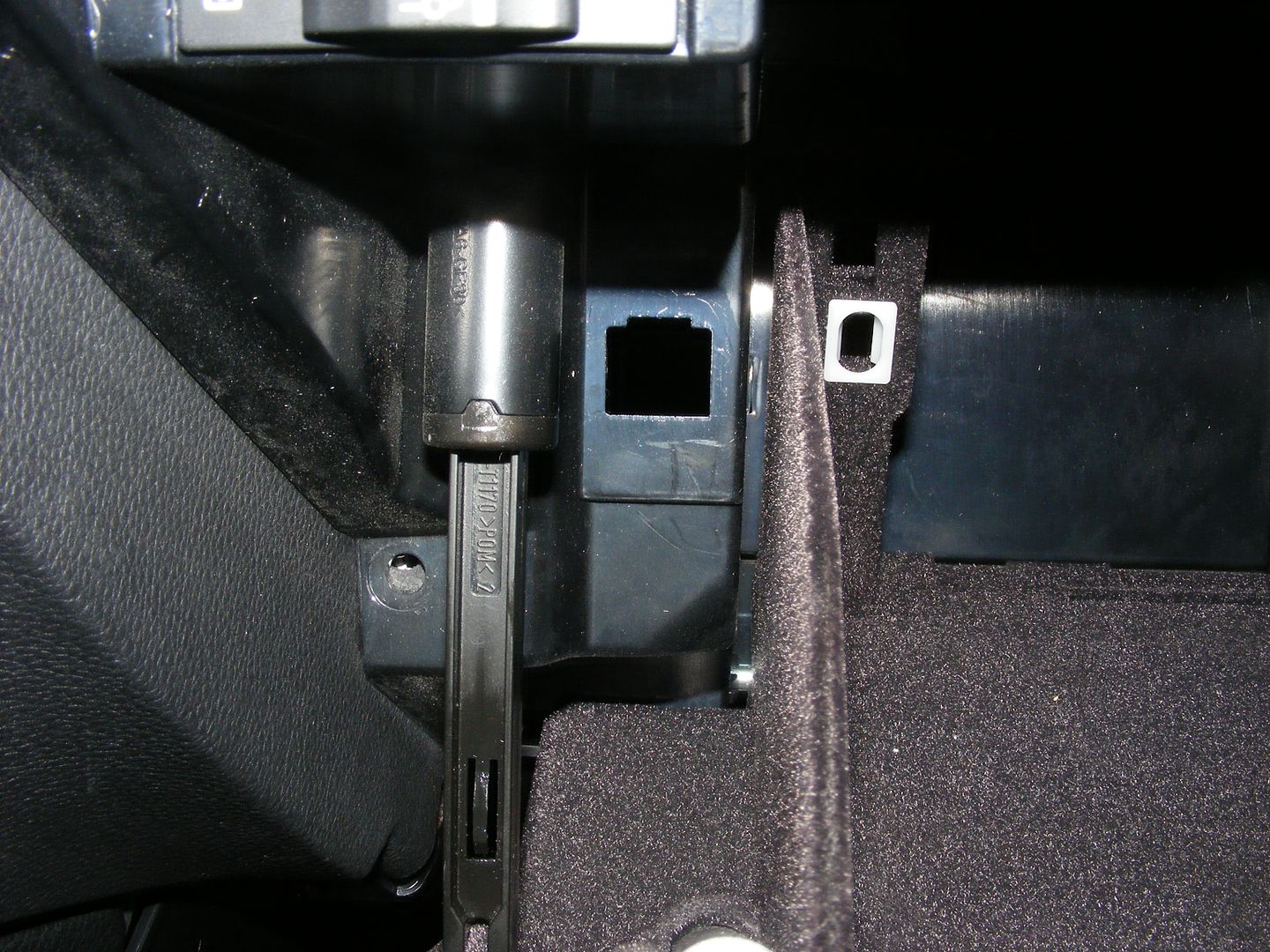
... just pry it out:
![Image]()
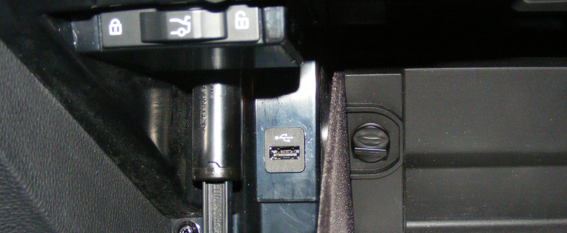
And insert the USB port (no need to remove glovebox, just "fish" the cable from the CIC area before installing it):
![Image]()
All connectors are color coded except the Power/CAN connector...
December 2009: New CIC (no programming at all yet), HD Screen cable, controller and console, used HD Screen and USB cable installed:
Legal screenshot...
Main menu (Navigation grayed out as it is not enabled)...
HD Radio...
HDD with 30+ MP3 songs already downloaded (320kps) thru the USB port...
Vehicle status (note that the vehicle shown is a Z4, once the CIC is properly programmed an E90 M3 will be shown)...
DVD -screw Twilight... bring fricking Blade to kill some suckers!!
MentholGuy's reverse camera for 2009 iDrive...
Assist/Bluetooth fully functional:
Notes for installation:
- CIC plugs right into the CCC Quadralock connector, Radio and GPS antenna.
- HD Screen installs -and uses same screws- in the dash as non-HD Screen. HD Screen requires new video cable and new Power/CAN connector, though:
HD Screen (CIC) on the left, non-HD Screen (CCC) on the right:
HD Screen video cable jack (round, 4 wires), Power/CAN jack (rectangular, pins #1-8 in a single row):
non-HD Screen video cable jack (rectangular, 8-wires):
non-HD Screen Power/CAN jack (rectangular, pins #1-12 in double rows):
The good news is that the Power/CAN wires (4 wires total) are exactly the same between the two different connectors, and they are located in exactly the same pin slots in both connectors (1, 3, 5 and 6).
The slot numbers are molded in the connectors and inside the connector jack (with the male pins) on each screen.
So it is a matter of getting the new connector with the used HD Screen (if possible) and removing the wires on by one from the existing double row connector and inserting each wire in exactly the respective slot in the new single row connector -wire in slot #1 from double row goes in slot #1 in single row connector, and so on.
Old, double row connector:
New, single row connector (bottom of photo, with USB port, USB cable and old double row connector with locking sleeve):
If you cannot get that single row connector with your used HD Screen (most junkers sell the HD Screen with the connector and the wires cut) then a ****ty solution -until you can get the proper connector, no P/N is available yet- could be either wrapping each pin with electrical tape or with shrink tubing and just plug each female jack into their respective male pins of the HD Screen (again, 1 to 1, 3 to 3, 5 to 5, and 6 to 6):
The elusive USB cable (no P/N is available so far):
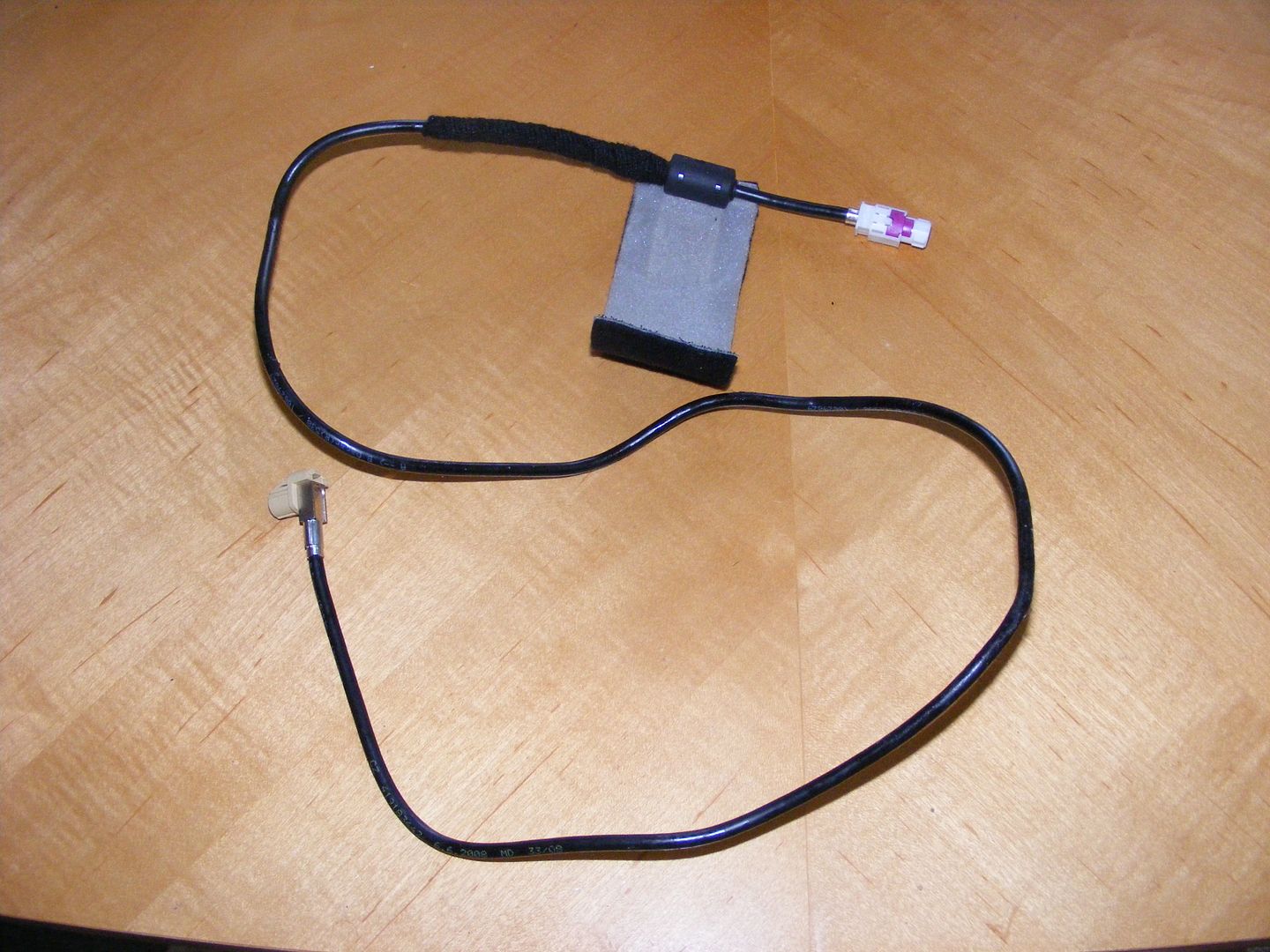
The video cable looks exactly the same as the USB cable but without that built-in circuitry/filter bump shown with the velcro wrapper above.
USB mount in glovebox is already made, just covered with a plastic plug...
... just pry it out:
And insert the USB port (no need to remove glovebox, just "fish" the cable from the CIC area before installing it):
All connectors are color coded except the Power/CAN connector...