UNDERSTAND DIGITAL MULTIMETER (DMM) TEST BASICS:
-
http://www.allaboutcircuits.com/vol_3/chpt_3/2.html
GATHER SEAT-OF-THE-PANTS DATA:
- Note exactly which warning indicators are lit (e.g., ABS & BRAKE & DSC)
- Note whether cruise control is working or not (sometimes implicates the passenger-side rear sensor)
- Note whether the speedometer (hence odometer & tripmeter) is working (sometimes implicates the driver-side rear sensor)
- Note "free play", "dead spots", & "centering" of the steering wheel (sometimes implicates steering column sensors)
- Note if normal ABS pulsation (ABS working) or skidding (ABS not working) when hard braking on sandy shoulders at 15 mph
- Note if
violent shudder (ABS working) or screech (ABS not working) when firm braking on top of speed bumps at 5mph
Note: It's not always just the sensor when the speedometer is also out with the 3 lights (the key is diagnosis)
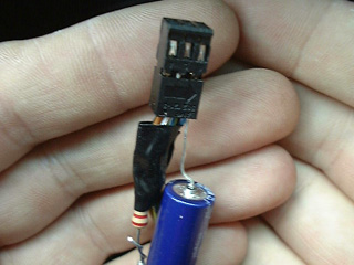
ACKNOWLEDGE ALL POSSIBLE (20) & MOST LIKELY (2) CULPRITS:
***8226; 1 BOSCH DC III Control Module 83 Pin (combined with the hydraulic unit in my E39, DSC III Bosch 5.7)
<==COMMON CULPRIT!
***8226; 1 Hydraulic Unit (combined with the control module in my E39, DSC III Bosch 5.7)
***8226; Hydraulic Unit contains: 2 pre-charge solenoid valves
***8226; Hydraulic Unit contains: 2 changeover solenoid valves
***8226; Hydraulic Unit contains: 4 intake solenoid valves
***8226; Hydraulic Unit contains: 4 outlet solenoid valves
***8226; Hydraulic Unit contains: 1 return pump
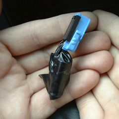
***8226; 2 Front Wheel Speed Sensors (Active Hall Effect) in the steering knuckles, secured with two 4 mm allen bolts
<==COMMON CULPRIT!
***8226; 2 Rear Wheel Speed Sensors (Active Hall Effect) in the rear wheel bearing carriers, secured with one 4 mm allen bolt
<==COMMON CULPRIT!
***8226; 1 Hydraulic Pressure Sensor (attached to the front-brake hydraulic unit in my E39, DSC III Bosch 5.7)
<==OFTEN MISDIAGNOSED!
***8226; 1 Steering Angle Sensor (located in the bottom of the steering column, near the flexible coupling)
***8226; 1 Rotation Rate, aka Yaw Sensor (combined with the lateral-acceleration sensor in my E39, DSC III Bosch 5.7)
***8226; 1 Lateral Acceleration Sensor (combined with the yaw sensor in my E39, DSC III Bosch 5.7)
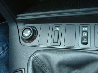
***8226; 1 DSC Switch (located below the radio in the cockpit)
***8226; 1 Hand Brake Switch (located on the hand brake assembly)
***8226; 1 Brake Switch (located on the brake-pedal assembly)
***8226; 1 Pre-Charging Pump
***8226; 1 Charging Piston (750iL only)
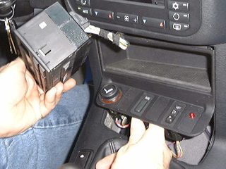
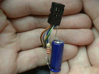
PHOTOGRAPH OF THE MOST LIKELY CULPRITS:
GATHER DESIRED TOOLS:
- Print this DIY out, bring a pencil to mark down your readings, and a drink
- Digital multi meter (DMM) with a diode-test capability & long, very narrow probes
- About six inches of 20 AWG stiff wire (to attach to your DMM probes and to the female ABS connector)
- A small piece of white or yellow tape so that you can label the positive stiff wire (to avoid confusion with the negative probe)
- T20 six-point Torx bit in a 1/4" socket with a 6" extension for removing the ABS control module
- 4mm allen wrench for removing the front wheel sensors
- Torque wrench (see torque tables below) for replacing components
- For rear sensors, a 10 mm socket, 8 mm socket, flat-head screwdriver, and needle-nose pliers might be required to remove trim.
- 1/4-inch wide 6-inch long standard flathead screwdriver for removing ABS harness connector clip
- CRC cleaner (or equivalent brake cleaner)
- Staburags NBU 12/K or equivalent grease (for speed sensors and connections in the housings)
GATHER OPTIONAL TOOLS:
- (maybe) 10mm socket for removing air filter box (easier access for some E39 models)
- Carsoft 6.5 or Peake Research or equivalent OBDII diagnostic scanner
- Oscilloscope (look for millivolt square waves coming from powered sensors as the wheel turns)
- Note: Carsoft 6.5 can't perform encoding, activation, or steering adjustments.
- Note: Bad ABS modules often report erroneous indications of a bad RR sensor in the OBD scanner reports
- Note: You must use new bolts for the ABS Control Module (according to the Bentleys)
PRICE OEM PARTS:
- Repair kit, control unit DSC, $1,120 + $112 (~10% tax) = $1,232 (often colloquially referred to as the "ABS control unit")
- Wheel sensors, front, $134 x 2 = $268 + $27 (~10% tax) = $295 total (some suggested EAC tuning for wheel sensors)
- Wheel sensors rear, $201 x 2 = = $402 + $40 (~10% tax) = $442 total (some suggested AutoHauz for wheel sensors)
- Front brake pressure sensor, $111 + 10% tax = ~$125 (measures 0-250bars of front-brake pressure, outputs 0-5 volts)
- Steering angle (yaw) sensors (in the steering wheel column or under driver's seat) ~$250 each (almost never needed)
- Hydro unit, DSC, $2,003 x 1 + $200 (~10% tax) = $2,013 (this "hydro unit" behind the ABS control unit is almost never at fault)
Note: If you replace the ABS module, you'll also need a $100 dealership recoding to your VIN & steering angles calibrated (apparently)
PRICE REBUILDING OF YOUR ABS MODULE:
- Module Masters ($105)
http://www.modulemaster.com/en/abs/ate_bmw_asc.php
- BBA Remanufacturing (8 days, $225)
http://www.bba-reman.com
- Auto & Truck Electronics ($105) EBAY seller's ID ATE1234, lifetime warranty, free shipping, quick turnaround
- Note: A rebuild of your ABS unit won't require VIN coding, activation, or steering angle calibration
PRICE A REBUILT ABS MODULE FROM ANOTHER VEHICLE:
- For a rebuilt part, most suggest
oembimmerparts.com,
one of our sponsors, at about $450 + $45 tax = $500
- Note: A rebuilt ABS unit from another vehicle requires a $100 dealership VIN recoding effort
QUESTION: What happens if you don't code the VIN & check steering angles ... (does the car blow up?)
CONSIDER FIXING IT YOURSELF (we need much more details to make this option viable):
- Open up the module & look for broken solder joints which can be sucked and resoldered (take pictures)
- Add point-to-point wiring where needed (we need more information to make this actionable)
- Replace diodes and any other weak parts with more robust parts (again, not very useful unless we know exactly what)
- Post before and after pictures so each of us can learn from the rest
CHECK BMW ERROR CODES:
- Locate the OBDII port, by law, in the cockpit, within 3 feet of the driver (above the driver's left knee in American BMWs)
- Hook up
Carsoft or
Peake diagnostic tools to the OBDII port to determine any error codes
- Cross reference
Carsoft error codes with the list of Bosch 5.7 error codes listed bellow (kindly supplied by
Max_VQ)
Note: Some say this check is of dubious value because a bad ABS module may show up as a bad rear sensor; always test the sensor itself!
BMW ABS/ASC Bosch 5.7 Table of error codes:
5 Right Rear Wheel Speed Sensor
6 Right Front Wheel Speed Sensor
7 Front Left Wheel Speed Sensor
14 Solenoid Valve Relay (check fuses 17 & 33)
15 Pressure Sensor/Pump Error
21 Module Memory Failure - ABS/ASC module is faulty
23 Incorrect Coding - ABS/ASC module is faulty
24 Wrong Impulse
30 Left Rear Wheel Speed Sensor
31 Open Right Rear Wheel Speed Sensor
32 Open Right Front Wheel Speed Sensor
33 Open Left Front Wheel Speed Sensor
50 Right Front Outlet Valve - ABS/ASC module is faulty
51 Left Rear Outlet Valve - ABS/ASC module is faulty
54 Left Front Inlet Valve - ABS/ASC module is faulty
55 ASC Intake Valve - ABS/ASC module is faulty
58 Gear Box Control Unit (CAN bus error)
59 DMER1 (CAN bus error)
61 Steering Angle Sensor Identification
66 Speed Sensor Voltage Supply
67 Intermittent Interference
75 Engine Speed Fault from DME
81 Pressure Sensor
82 Open Yaw Rate Sensor
86 ASC Cut-off Valve Rear Axle
88 Precharge Pump
89 Low Voltage
90 Temporary System Deactivation
94 DDE Fault/Yaw rate sensor
97 Steering Angle Sensor
10 Brake Light Switch
108 SN Control
112 Open CAN to Instrument Cluster
114 Pressure Sensor Offset
117 Brake Light Switch Failure
118 DME Status-Internal Error
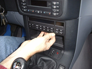
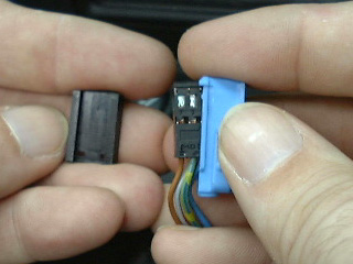
REMOVE ABS-MODULE CONNECTOR:
- Facing the engine, slide the plastic retaining clip to the right with a 1/4 inch flathead screwdriver.
- It is a plastic retaining clip, so do be careful not to break it; it slides over about 1 1/4 inches or so.
- Once the clip is fully to the right, lift the electrical connector up
- Notice the female (blue) connector with 42 holes (and very tiny lettering)
-
DO NOT STICK YOUR TEST LEAD INTO THE SQUARE HOLES!
(Only put test leads into the larger rectangular holes next to the square holes.)
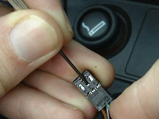
NOTE ABS-MODULE PINOUT: (notice the test lead holes)
- Each wheel sensor circuit has a set of two wires in the ABS connector (
pinout kindly supplied by
540iman)
- ABS-connector pins 13,29 = Left rear wheel sensor (also affects speedometer & odometer & tripmeter)
- ABS-connector pins 30,31 = Right rear wheel sensor (also affects cruise control)
- ABS-connector pins 28,12 = Left front wheel sensor (
some say it also acts as a steering angle sensor)
- ABS-connector pins 15,16 = Right front wheel sensor (
tells gearbox electronics how fast you're going)
Note: These pinouts are in the same order of the diode action of each sensor (do not reverse these numbers)
Note: Don't confuse with the brake pad wear sensor, which is only located on the front left & rear right wheel & which uses a black connector.
Note: ASC cars have only two sensors, one on the front right and the other on the rear left wheel.
UNDERSTAND WHEEL SPEED SENSORS:
Note: The wheel speed sensors are two-wire hall effect transducers which send a digital square wave signal with a low of .75 volts and a high of 2.5 volts to the DSC control unit. Each sensor receives a well-regulated 8 volt power supply from the control module through one wire. The ground path for the sensor is through the second wire back to the control module. The signal is generated by a pulse wheel affecting the voltage flow through the hall element in the sensor. The pulse wheel is integrated into the wheel bearing assembly, behind the seal. This protects the trigger wheel from foreign substances which may affect the wheel speed signal.
TEST WHEEL SENSOR CIRCUIT FROM THE ABS CONNECTOR (also checks wiring circuit):
OPTIONAL: Jack car up (so that all four wheels can be spun to test voltage & resistance fluctuations of the hall-effect sensors)
- Turn the car off and remove the key from the ignition.
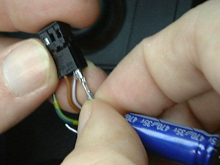
-
TEST 1: Switch the DMM into the diode test position
- Wrap a stiff 20AWG wire onto the ends of your DMM probe for sticking into ABS-connector pins
- Label the positive 20AWG wire with white tape so that you won't get confused as you switch back and forth
- Stick the ends of the wire into the appropriate female holes of the ABS connector (13-29, 30-31, 28-12, 15-16)
- In one direction, you should see 1.7 to 1.8 volts (note the pinouts mentioned are in order, positive to negative)
- In the other direction, you should see OL or some other infinite reading (open circuit)
-
TEST 2: Switch the DMM into resistance checking mode (optional)
- You should see around 3.3 Mega ohms in one direction & approximately twice that in the other direction (
but some say more)
-
TEST 3: If desired
spin the wheel at about 1 revolution per second, by hand (
the resistance should fluctuate as the wheel spins)
-
TEST 4: Switch the DMM into millivolt mode (optional) & again spin the tire & wheel assembly by hand (test-lead polarity won't matter)
-
You should read between 1 and 5 mV when you spin the hub (no voltage implicate the sensor or circuit)
- OPTIONAL TESTS BELOW REQUIRE FLYING LEADS WITH THE IGNITION SYSTEM ABS SYSTEM CONNECTED & POWERED UP:
-
TEST 5: Swith the DMM into the 10v and attach flying leads to the sensors with the power on
-
You should see the voltage going to the sensor and the return signal
- Expect a baseline voltage of about +5 to +12 volts depending on the ABS system (does anyone know this value?)
- Expect that baseline voltage to the sensor to change (by how much?) as you spin the wheels
-
TEST 6: Hook an oscilloscope with "flying leads" to the ABS sensors (notice that the ABS system must be powered)
-
You should see nice clean square waves generated as you hand spin the wheels at about 1 revolution per second.
Note: The oscilliscope can
detect problems that can't easily be found with a DMM
(A scope pattern for a wheel speed sensor should show a classic sine wave alternating current pattern that changes both in frequency and amplitude with wheel speed. As the wheel is turned faster, signal frequency and amplitude should both increase. Damaged or missing teeth on the sensor ring will show up as flat spots or gaps in the sine wave pattern. A bent axle or hub will produce an undulating pattern that changes as the strength of the sensor signal changes with every revolution. If the scope pattern produced by the sensor is flattened (diminished amplitude) or is erratic, it usually indicates a weak signal caused by an excessively wide air gap between the tip of the sensor and its ring, or a buildup of metallic debris on the end of the sensor. A weak signal can also be caused by internal resistance in the sensor or its wiring circuit, or loose or corroded wiring connectors.)
INTERPRET DIODE-TEST RESULTS:
- If the DMM, in diode mode, reads infinity ("OL") in both directions, you've got a bad sensor or circuit
- If the DMM, in resistance mode, reads much greater than 7Mohms, you've got a bad sensor or circuit
- If all 4 sensors read OK, it's most likely the ABS control unit.
- If you think you found two bad sensors, you probably messed up.
- Rarely is the cause due to bad steering angle (yaw/lew) sensors
- Rarely is the cause due to a bad hydro unit
- The problem is almost always a wheel rotation sensor or the ABS control unit
ACTUAL RESULTS ON MY 2002 E39 THIS MEMORIAL DAY WEEKEND:
DOUBLECHECK WHEEL SENSORS AT THE WHEEL:
Note: You can run this test w/o removing the wheel but access to the sensor connector is easier with the wheels off the E39
- If one or more sensor circuits test bad in any of the three tests above ... then ...
- Locate the sensor blue connector in the rear of each front wheel well by turning the front wheels
- Easiest to first locate the sensor (bolted on the wheel carrier near the hub) and trace its wire back to a black plastic hinged box housing
- Open the locked hinged plastic rectangular black box with a small flathead screwdriver
- Locate the blue wheel sensor connector (next to a black brake wear sensor connector)
- Pull the blue wheel sensor connector out of the box and disconnect the two sides
- Re-check the sensor there with the diode function of the DMM
CHECK WHEEL SENSORS OFF THE VEHICLE:
- If any sensor still checks bad, pull the sensor off the vehicle for a closer inspection
- Chock wheels and jack E39 BMW and jack stand at the 4 jack pad locations
- Remove 4mm allen head bolts to sensor retention screw (two retaining bolts for fronts, 1 bolt for the rears)
- Pull wheel sensor out of hub assembly, straight up.
- Clean with CRC electronic cleaner
- Check with DMM diode-test meter as before
- Grease with Staburags NBU 12/K or equivalent grease
- Replace sensor back into hub assembly, snug tighten to 6 foot pounds
- Replace rear wheel, tighten to 82 to 96 foot pounds
Note: You might wish to swap sensors on the same axle when replacing so as to obtain further diagnostic information should an anomaly occur.
Note: Here is a picture of a dirty and cleaned sensor (magnetic particle buildup)
TEST BRAKE PRESSURE SENSOR (aka HYDRAULIC UNIT PRESSURE SENSOR):
- This test procedure kindly suggested by Max_VQ:
- Given 250 bar = 3,626 psi, and given 0-5 volts linear proportional output, 3,626 psi/ 5v = 725.2 psi/volt or 1.3 mV per psi.
- With the ignition on, measure the voltage on the pressure sensor while someone is pressing hard on the brake pedal
- My guess is that should create about 3,000 psi of force and should show around 4.13 volts.
- At rest it should show very close to 0 volts
Note: The front-brake pressure sensor provides a 0-5 volt linear voltage signal to the DSC III control module which is proportionate to how hard the driver is pressing on the brake pedal, from zero to 250 bars (3,626 psi), spanning (a) no braking, to (b) partial braking, and to (c) near-ABS-regulation state braking. This brake pressure sensor has three pins (a) power, (b) ground and (c) the 0-5 volt proportionate signal.
Note: By way of comparison, the Corvette also has a brake pressure sensor to indicate how hard the brakes are being applied; it monitors pressure from 0 to 2000psi generating a corresponding signal of 0.20 volts to 4.80 volts.


")