BMW Forum - BimmerFest BMW Forums banner

E39 M52 owners: Please check your realoem diagrams against your vehicle & help us out

43K views 26 replies 11 participants last post by  sapote  
#1 · (Edited)
E39 M52 owners: Please check your realoem diagrams against your vehicle & help us out

To M52 owners:

  • 1997***8211;2000 528i - 2.8 L M52B28 I6, 190 hp (142 kW; 193 PS) USA
  • 1996***8211;2000 520i - 2.0 L M52B20 I6, 110 kW (150 PS; 148 hp) non-USA
  • 1996***8211;2000 523i - 2.5 L M52B25 I6, 125 kW (170 PS; 168 hp) non-USA
  • 1996***8211;1999 528i - 2.8 L M52B28 I6, 144 kW (196 PS; 193 hp) non-USA
  • 1999***8211;2000 528i - 2.8 L M52B28 TU I6, 144 kW (196 PS; 193 hp) non-USA
May we ask M52 owners to confirm the following?

GIVEN:

  1. The M54 diagram for the fuel pressure regulator is inconclusive:
  2. The M54 realoem diagram for the CCV is wrong:
  3. The M54 diagram for the F-connector is dead wrong:
We suspect the following happened between the M52 & the M54:

  1. BMW moved the fuel pressure regulator from the engine bay to under where the driver sits...
    • So they simply ERASED the relevant parts in the diagram (notice they even erased the location dot!). The vacuum hose doesn't show any connection whatsoever!
  2. BMW capped off the CCV vacuum port
    • In this case, they didn't modify the diagram at all so it's wrong in that hose #6 is actually endcap #15 (not shown on the diagram or in the parts list)
  3. BMW changed the L connector to an F connector so that the hose that previously got suction from the CCV would now get suction from the F connector
    • Again, they didn't bother to fix the diagram; so the diagram is confusing at best and dead wrong in many ways!
These changes are partly the reason for all the confusion (which is noted on other threads - but which isn't fully outlined in any!).

TO BMW M52 OWNERS:
Can you kindly confirm what we've said above holds water?

If you have the M52 engine, we'd expect to see:

  1. Your fuel pressure regulator is in the engine bay
    • Ours is under the driver; but realoem doesn't show that
  2. Your CCV vacuum port is connected to that fuel pressure regulator
    • Ours is capped off; but realoem doesn't show that
  3. Your rubber elbow has an L connector on top
    • Ours has an F connector; but realoem doesn't show that
Is that what you see?

Specifically, a picture of your "L" connector would be nice.

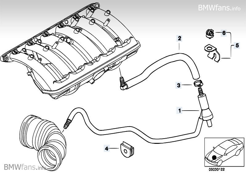
Here is our "F" connector & one of the diagrams which is wrong:
- Correcting the F-connector errors in the realoem diagrams (1)

Image
 
#3 ·
The fuel pressure regulator on my M52TU/E46 is definitely not on the fuel rail or in the fuel filter. I believe it's in front of the fuel filter on the 2/3 distribution valve. I also don't have an L connector on the intake boot. But... the vacuum port from the CCV goes up to a metal line on the fuel rail (to the FPR?).
 
#6 · (Edited)
No L/F/T fittings. It goes straight into the hose.
Actually, it 'has' a fitting. It's shaped like a straight tube (if that diagram is correct).

That makes THREE kinds of connectors: F, L, and now I.

Yours is the FIRST post that says you can trust 'your' Realoem diagram; which is why I hadn't gone there for the M52. It's also the first post showing an "I" connector. I tried to look it up on Realoem but I didn't know what year and model you had.

If we can trust the M52 diagrams, that's a whole different (easier) story.

For example, here is a USA automatic 528i sedan born in January 1997:
- Engine => Vacuum control => E39 528i Vacuum control - engine
Image
 

Attachments

#8 ·
Does this help you at all?
Yes. The picture helps a LOT.

Reproduced here, at 640x480 pixels.
Image


So it seems that it is, indeed, an "L" connector (and that it doesn't pop out of the top of the snorkel like the F connector does, but, apparently from the side.

I presume the other end of that vacuum tube goes to your brake booster, right?
 

Attachments

#10 · (Edited)
Thank you. They show the differences, side by side, perfectly!

BTW, over here, we just found yet another error in the M54 diagrams:
- Engine => Vacuum control => AIR PUMP F VACUUM CONTROL

Apparently the rigid plastic pipe along the SAP valve side of the engine is curved on the M54 but it's shown straight with an additional hose in the diagram. Steve530 kindly colored the pipe yellow, overriding the errors in the Realoem (diagram for the M54 anyway).

Is this yellow plastic pipe (#3 below) straight in the M52, or curved around the back of the M52 engine?

Image
 
#12 · (Edited)
As best as I can tell, it curves around the back of the M52TU engine.
The rigid plastic pipe that reputedly curves on the M54 is on the 'other' side of the engine (i.e., it's on the passenger side, connected to the SAP valve flexible hose on the front end and to the electrical valve on the rear in back of the engine).

That rigid plastic pipe (see #3 in the realoem diagram in my prior post) is shown as 2 pieces (a straight pipe and a curved flexible hose) in the realoem diagram; but there are reports that it's one curved plastic piece and not one plastic piece + one rubber piece.
Image


BTW, on the other side of the engine (i.e., on the driver's side), here is your PDF in JPG format so that it's easier for all to see the M52TU "L" elbow and the M54 "F" connector, in situ.
Image

I must admit, these two pictures are worth a thousand words in clarifying the real situation (which the BMW diagrams screw up royally).
 

Attachments

#15 ·

Attachments

#16 ·
Hey guys. I forgot to check out the date, but if those were of the M52 I am sorry to tell you how they do not match my M52. I even went to the dealer for a certain cooling hose below the radiator and he said this is your hose. I argued with the guy telling him that is not the hose because I took it off and he found it in another diagram on another year car etc. Not sure who is making these mistakes, but eh. Hope these pics help more than confuse. Let me know if you need anymore for the M52. I will try my best. I had these off to replace the starter and bench test the old one. I knew it was shot or I would've tried different methods for testing.
 

Attachments

#18 · (Edited)
Thank you for these great pics.


Part of the confusion may come from the fact that the 528i's produced from 09/97 (late) to 09/98 (early) ie the '1998' 528i were different from the ones before or after. These pictures really helped me a lot. I'm about to test my fuel pressure this Friday (Nov 29. 2013) and was trying to locate an FPR online. (just too dumb to wait until tonight to check the car - I was hoping to get answers without having to go under the car in a snow storm).

I beleve that for a year or two after the 1998 528i, the FPR was located underneath the car near the fuel filter as part of the 'M52TU' generation, before being moved into the filter in the M54 generation.

Thanks again for the great pics with the clear labels and coloured tubes. You're a prince!
 
#21 ·
Dear BMANZetc.

I humbly suggest that you might want to put the last 7 characters of your VIN into RealOEM.com. I'm beginning to think that you might have a 1997 528i - according to their diagrams anyway. The 1998 528i shows that the fuel-attached FPR is not a part of that year's model (the part numbers are not included in the diagram).

Cheers.
 
#22 ·
This isn't the first time it has been brought up. I was at BMW and get said does the hose look like this? I had to tell them there diagrams were wrong in the system as I know what my hose looks like as I took it off haha. They found the hose on their 1999 diagram. Mine is indeed a 1998 as shown on the emissions label, veci, door label if you will, and registration ***128516;. I did just think of something though. It was almost identical and still and m52, but I didn't pay close enough attention as I only had the engine 2 weeks. I had a 1997 I swapped engines with because the 2 week old cars head gasket blew. That engine believe it or not only had 140k and guy appeared to take good care and only to dealer just my luck. Was going to do a head gasket job and so on when I had some extra cash. The engine in now from my older parts car (mine before I lost reverse) now in current car (pics above) has 309k and still going. Do these die? I looked at both diagrams for m52 and both hooked up the same. I only have 2 codes after driving 40-50 miles. CA 02 sensor control limit cylinders 1-3 and E3 0s sensor adaption limit reached cylinders 1-3. Nothin else. Everything appears to be buttoned up tightly. Happy Thanksgiving or holidays whichever you celebrate!!
 
#23 ·
Happy Thanksgiving to you, as well.

Did I understand correctly? You have a '97 engine in a '98 body? That would explain things.

Beyond that, I've been told by parts sales staff that 09/1997 was a funny month in that the early part of the month cars were different in some ways from the later part of the month. Unfortunately I don't have any details.

This is more fun than The Da Vinci Code. heh. :thumbup:
 
#25 ·
Euro RHD M52 (1996) 528 vin BV73231.
Copy and validate most of BMWMANZ2's photos as similar.
+ No F or L connector on top of the elbow boot between MAF and TB
+FPR is on top of fuel rail for me too.
+CCV has drain to dipstick and connects to intake manifold via grommet. No other vacuum hoses on CCV.
 
#26 ·
Well this is an old thread, but perhaps this will add to additional clarification on yet another version of the mighty M52 engine. Mine is in a 2000 528i, automatic.
I have the L shaped connection on the top of the intake hose, not the F connector. Hose goes to sucking jet. I also dont have a FPR mounted near or under intake
manifold. Its down below car, drivers seat, around the fuel filter. When I replaced fuel filter last year, it was not attached to FPR, it is a separate part, so I left it alone.

Regarding the vacuum hose from the SAS pierberg valve thingy, front right side of engine, that small hose runs back along block via various soft, then thin brittle hose
to curved soft hose again, and finally ending at the side nipple of that little valve under manifold backside, perhaps the evap value not sure of name. Has a nipple at top and one at side.
The end or top nipple attaches to a short hose, to the black/white one way check valve, then attaches to a nipple on the firewall side of the intake manifold. The white and black
one way value is called perhaps purge valve? This tiny little value has the black side facing the intake manifold.

And lastly, the new (OEM) CCV I just installed has a soft vacuum line running from the nipple on the ccv (the one capped on others cars) to the front of my fuel rail
(which is just tiny dia. metal pipe running from the front of fuel rail to rear as if a metal straw) then at the rear end of this tube/pipe another soft vacuum hose exits pipe
over the brake booster area, where it picks up that hard brittle plastic tubing which goes down underwheelwell to that FPR which sits infront of the fuel filter. So essentially,
the CCV nipple is attached directly to the FPR under drivers seat, but takes a long path along fuel rail, behind intake manifold, down to fuel filter to do its job.

I was only in there replacing the two leaking 14 y.o. (148,000 mi.) orig. plastic heater pipes, requiring me to remove the intake manifold, since I had replace all other hoses
two years earlier, but kept putting this off until a friend/indy said when those plastic pipes turn from black to a brown, you are on borrowed time, luckily they only weeped
and did not rupture. This allowed me time to buy everything I needed to replace while in there.

For those interested in doing this job, it is very involved, time consuming and requires great attention to detail, but very rewarding. While in there, since my care is aged, I
replaced knock sensors, the two plastic pipes that came with o-rings, manifold gaskets just because I removed IM.,Throttle body gasket same reason, CCV, as it was aftermarket,
and I wanted OEM, and wanted peace of mind, as I hope to not do this IM removal again. I purchased a new crankposition sensor, but saved for another day. It is diff. than one in car,
a redesigned one with additional connectors, and required snaking around all the way up to vanos solenoid. Was worried if it didnt operate correctly, I'd be at square one again, so
chose not to risk problems with the new for old swap, I'll wait for failure and a code to go thru that job.

I checked and replaced as needed any vacuum hoses, and the little black and white one way purge value to rear of manifold. Sucking jet and hoses to underside of manifold looked good,
and I chose to leave them alone. While inspired to do this job, I also installed a new HEPU waterpump, belts, all pulleys and rebuilt (regulator $30 for Bosch) an Ebay alternator I picked up
for $60. Might also note, I DID NOT removed the OFH, there was enough room to replace two heater pipes without doing so.

Afterwards, my car started up, gave me a CEL and I found one sensor I had forgotten to attach, only other slight problem was my wrench whacked an old oil pressure sensor on back of OFH, which I replaced
for $9 from Ebay. It was so old and brittle from heat, it snapped off the threaded part, but car ran with old one in there, but no sensor attached until I got the new one in mail, and installed today.
Hope this helps, and thanks for all the direction everyone.
 
#27 ·
On the top of the CCV is a spring loaded valve which closed off the path from the oil separator to the intake manifold at idle (high vacuum), and opened the path at higher rpm (low vacuum) to pull the gas from CCV into the intake. My question is that if the path is closed during idling then where does the gas from the crankcase (valve cover) go with additional blowby gas got into the crankcase if the car sit idling in traffic?