BMW Forum - BimmerFest BMW Forums banner

WHERE does the CCV vacuum source port go for the E39 CCV valves that are not plugged?

78K views 51 replies 14 participants last post by  bluebee  
#1 · (Edited)
EDIT:

  1. On the M54 CCV, the vacuum port is closed off with an endcap
  2. On the M52, the vacuum port of the CCV provides vacuum for the fuel pressure regulator
  3. On the M62, the vacuum port of the CCV provides vacuum for the sucking jet pump
-----
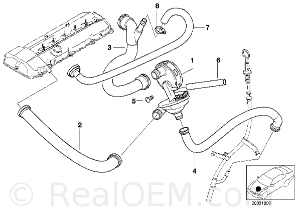
I'm curious WHERE the vacuum hose goes for the E39 CCV valves that do NOT have their CCV vacuum port plugged.

My theory (which is just a guess) is that this plugged port #9 on the back of my 2002 M54 engine is where the CCV vacuum hose 'would' have gone had it been in place.
- Engine => Vacuum control => AIR PUMP F VACUUM CONTROL

That plugged port is also shown as #17 in this diagram:
Engine => Intake manifold => Intake manifold system

Do you think this plugged port is what WOULD have been connected to the CCV if the CCV port wasn't also plugged?

Image

NOTE: There is a typo in the caption; it should be "BTW, note the cracked condition of that endcap" (since replaced as explained here):
- How to locate all the vacuum hoses in the E39 engine bay
NOTE: We found the part number & size for the endcap over here:
- M54 vacuum hoses ... what diameter ... what brand ... what material ... what length?
NOTE: See also a thread which asks what the vacuum port on the CCV actually does:
- CCV vacuum hose important?
 
#8 · (Edited)
why does this matter?
The more we learn what BMW was thinking when they designed the M54 engine, the better we understand our engines.

I recall a post where someone applied intake vac to this port on CCV of M54 and achieved less oil consumption
Exactly!

Perhaps, if we understand what port BMW originally intended to deliver vacuum to the CCV, and if we then apply that vacuum via that port, 'something' useful may result from the experiment.
 
#5 ·
suscribed

I am curious about this as well.
My M52TU uses this, but not my M54. M54 has more CCV issues and mayo. I worry about hydro-locking the M54 every winter.
I recall a post where someone applied intake vac to this port on CCV of M54 and achieved less oil consumption, which I experience on M54 and NOT with the M52. Curious if it would run cleaner in winter, but am afraid to mess something else up with balance of M54 harmony.
I will try to research this after work.
 
#7 ·
It matters to me


I suspect this may be why the M52s don't have the same issues as the M54 CCV. Another difference is the cooling system design. M54 is designed for hotter bottom end (reducing friction) and cooler head (increased combustion efficiencies). Perhaps BMW eliminated this vac hose for other reasons and the result is decreased CCV performance. Rather than blaming this issue, they decide to throw insulation at the problem and blame it on cold weather and ethanol gas (which I'm sure doesn't help with condensation). I'm an engineer for a large corporation and I am surrounded with instances when business politics and accounting can really impede otherwise good products.
Daily commute for M54 is 30 minutes each way mainly hwy speeds. Oil is changed every 6k with M1 0w-40. I'm not from the "short drive cycle" / "high OCI" sample.
 
#9 ·
The vacuum port on the CCV valve went to the fuel pressure regulator on the M52 engines--the M54 engine the port is capped off-----on the M54 engines the fuel pre--reg derives vaccum from the small vac hose that goes into the air intake duct--right after the maff--along side of the vac hoes for the jet suck pump
 
#15 · (Edited)
The vacuum port on the CCV valve went to the fuel pressure regulator on the M52 engines
Interesting! Very interesting!

I am 'not' attacking your assumption by asking the clarifying questions below ... but if that statement above is true, everything I 'thought' about the CCV vacuum source is wrong.

So ... I 'must' ask ...

If the hose on the M52 goes from the CCV to the fuel pressure regulator, would I be correct in assuming the DIRECTION of air flow MUST be FROM the fuel pressure regulator TO the CCV?

If so, having the CCV be the 'source' of vacuum is directly the opposite of the user-annotated (mostly by cn90 and me, IIRC) diagrams sprinkled all over the place.

For example, look at the pictures & diagrams here:
- How to test the crankcase ventilation (aka CCV, CVV, PCV, CPV, & OSV) pressure regulating valve system (1)

Image


Both the picture above (from cn90) and the diagram below (annotated by me), assume the CCV vacuum port is connected to a 'vacuum source'.
Image


So, to move forward, we have to clarify how the M52 worked before we can begin to understand the M54.

QUESTION:
Q: In the M52 engine, what is the DIRECTION of air molecules in that vacuum hose?

Said in other words:
Q: In the M52 engine, which end of the hose is the vacuum source (i.e., the CCV or the fuel pressure regulator)?
 
#14 · (Edited)
You need to reread my thread. I am not promoting a "don't bother to think about it" attitude. My concern is what BB is suggesting when she says "Maybe we'll find a way to hook it back up to the CCV". What I am saying is don't even consider a radical modification of your CCV :yikes: unless you really know what you are doing. Clearly, Poolman knew what he was doing. But I don't see anyone repeating his CCV solution (the oil catch can). BB has been on this forum for awhile and she has never demonstrated a willingness to step beyond her mechanical capabilities (which is wise). Neither have I, for that matter. So now she is contemplating a redesign of the M54 CCV system? I simply don't recommend it. In my opinion, anyone that thinks they know more about these cars than the factory has an overinflated opinion of their own knowledge and abilities. These cars are very sophisticated machines. And yes, they are far from perfect. The collective experience of this forum's owners is a huge asset but nothing said here should be taken as gospel. This is the Internet, where anyone can say anything! :rofl:

The Vanos seals is a great example of a major problem applicable to all M54s, M52s, etc. that has been modified by the aftermarket. Beisan Systems diagnosed the problem, reported it to BMW (who ignored them) so they redesigned the seals and wrote up a detailed DIY to replace them. Even with the glowing remarks from people who did this job (Poolman), it still took me awhile to muster up the willingness to open up my engine to do this. If you do anything to your car, do this, for the performance improvement.

WRT to the CCV specifically, there is no aftermarket solution other than the insulated hoses. Consider the scope and magnitude of the CCV problem before you consider any corrective action you may regret. First, do a search to determine how many hydrolocked engines have occurred due to CCV issues. It is not many (more common on the X5). Second, a failing CCV is rarely an immediate catastrophic event, unlike a cooling system or DISA valve failure . A failing CCV system typically begins with increased oil consumption and a smokey exhaust. Can it fail catastrophically? Yes as in Doru's case. But it can be corrected by simply (actually a PITA) replacing the CCV and hoses. Modifying your driving habits can help to reduce the likelihood of a problem. All in all, the CCV is flawed system but not what I would consider a major deficiency in the M54 design. I personally feel this is the best designed engine I have ever owned.

My advice is simply this: "A (wo)man's got to know his limitations". Learning more about something is one thing. Doing something about it is an entirely different matter. Just one guys opinion. :roundel:
 
#16 ·
I don't know anything about the M52 engine vacuum routing, but I may be able to answer you question.

I still have the CCV I removed a few weeks ago. I took it apart, so I think I can explain how it works.

The bottom cone shaped part is a cyclonic separator. If you look at the entrance of the vent tube, you'll see that it enters the cone at a tangent. The blow-by gasses and oil hit the sides of the cone forming a vortex. The oil droplets are thrown against the side of the cone and fall into the tube that drains to the dipstick. The gasses are forced through the center of the vortex up through the "L" shaped tube that connects to the upper part of the CCV.

The connecting line that connects the upper part of the CCV to the manifold supplies a vacuum. The upper part has a diaphragm and spring. When there is a high vacuum at idle, the diaphragm moves to close off the connecting line. When the vacuum drops at high engine speed, the spring pushes the diaphragm back allowing the gases in the cyclonic separator to flow into the manifold. I think this is typical design for a PCV system because it allows blowby gases in the manifold at high engine speed and blocks the blowby gases at idle.

The "L" shaped tube has the nipple. When the diaphragm in the upper part is open, the nipple will have the same vacuum as the manifold. When the diaphragm closes, the "L" shaped tube is closed off from the manifold vacuum, so the nipple will be at the same vacuum as the crankcase.

So it seems likely that the nipple was indeed a vacuum source for a fuel pressure regulator. At high engine speed, a vacuum would be applied to the FPR to increase fuel flow. At idle, the high manifold pressure the closes CCV diaphragm and no vacuum would be applied to the FPR through the line connected to the nipple.

If you connect that nipple to the manifold, it will pull blowby gases into the manifold at idle. Because the engine speed is low, that may not be a good idea. .
 
#18 · (Edited)
I think I can explain how it works.
That was a wonderful explanation! (As was the previous one about the 'blanking cap' over in your Bimmerforums.co.uk reference.)

To ensure value added, I will add both explanations to the annotated pictures in order to further leverage those revelations to other CCV-related threads (& get the word out).

The most interesting comment was this one:

it seems likely that the nipple was indeed a vacuum source for a fuel pressure regulator
If the CCV center-section port is a vacuum 'source', that changes everything about this thread!

Besides making all the diagrams wrong in an instant, it also instantly negates the 'need' to find the 'missing' vacuum port on the M54!

Believe it or not, a key question might be the shape of your F connector!

You may wonder why I ask that ... and I'll explain in due time ... but first, may I ask if the F connector on vacuum-equipped CCVs is actually L shaped as shown in the diagrams in this recent thread?
- Correcting the F-connector errors in the realoem diagrams (1)

M54 engines with end caps need those end caps replaced to prevent vacuum leaks.
It looks like the M52 is the only E39 to use this CCV vacuum source?
Apparently on the S62, this CCV-derived vacuum port does not exist.
On the M54, it seems degradation of this endcap can indeed be a source of vacuum leaks.

In fact, there is a simultaneous quest to find & replace the two, three, or maybe even four endcaps over here:
- What are the vacuum endcaps in the E39 engine (1)

1) #17, 7mm (between 17/64" & 19/32") endcap for the M54 engine rear vacuum port.
2) #15, 3.5mm endcap (between 1/8" & 9/64" ID) for the CCV valve vacuum port.
3) #15, 3.5mm endcap (between 1/8" & 9/64" ID) for the air pump vacuum port if you don't have an air pump (see details from Steve on this below).
4) Some exhaust systems seem to have a 7mm endcap?
Q: In the M52TU engine, what is the DIRECTION of air molecules in that vacuum hose?
A: Molecules move TOWARD the CCV (from the fuel pressure regulator).

Q: In the M52TU engine, which end of the hose is the vacuum source (i.e., the CCV or the fuel pressure regulator)?
A: The CCV, for this question, can be considered the vacuum source (not the FPR).

Image

REFERENCE: M54 engines - guide to finding vacuum leaks
REFERENCE: Steve530 in this thread
Image

REFERENCE: Detailed DIY for Crankcase Ventilation Valve Overhaul for the M52TU Motor
Image
 

Attachments

#19 · (Edited)
Blue Bee--told ya before--don't second guess me --when I had problems with oil usage--one of the things I to make the fix with was--I ran a vac line from the ccv port we are referring to and then hooked the other side to one of the ports at the back of the intake manifold. This helped some, but not enough. I ended up with my oil catch can and putting the complete crankcase in a controled vacuum utlizing a common PVC valve from a big block Ford--Ford products work well everywhere
 
#20 ·
Blue Bee--told ya before--don't second guess me
:) We are thinking the same thing but you got the jump on me, by, oh, I don't know, a few years probably!

As soon as I saw an empty unguarded undefended port, my mind wanted to make good use of that otherwise-wasted vacuum source for my purposes quicker than Nancy Pelosi could wrap her hands on a new source of revenue to be squeezed out of the hard-working people!

The thread you're referring to is probably one of these, which I will read:


I ran a vac line from the ccv port we are referring to and then hooked the other side to one of the ports at the back of the intake manifold
I'm going to have to 'slowly' read (and re-read) your solutions ... but may I ask the first obvious (perhaps dumb) question that arises?

Assumption:
Since we now know that the ccv vacuum port was intended to be a 'source' of vacuum for the fuel pressure regulator ... (i.e., the movement of molecules was intended to be INTO the CCV valve)...
Question:
What is the logic of benefits from reversing the flow from that of the initial design?

Note: I'll first read for the answer in the threads ... but that's the first question I have since I now realize the CCV was never designed to be attached to a vacuum source at that nipple in the middle of the CCV.
 
#22 · (Edited)
Interesting ideas.
The confusion arises because the BMW schematics seem to be as badly written as a cellphone law by Joe Simitian!

I think we wouldn't have half this confusion if the realoem diagrams were closer to correct.

To that end, I asked M52 owners to confirm the latest hypothesis to fall out of this thread:
- E39 M52 owners: Please check your realoem diagrams against your vehicle & help us out

May we ask M52 owners to confirm the following?

Given:

  1. The M54 diagram for the fuel pressure regulator is inconclusive:
  2. The M54 realoem diagram for the CCV is wrong:
  3. The M54 diagram for the F-connector is dead wrong:
We suspect the following happened between the M52 & the M54:

  1. BMW moved the fuel pressure regulator from the engine bay to under where the driver sits...
    • So they simply ERASED the relevant parts in the diagram (notice they even erased the location dot!). The vacuum hose doesn't show any connection whatsoever!
  2. BMW capped off the CCV vacuum port
    • In this case, they didn't modify the diagram at all so it's wrong in that hose #6 is actually endcap #15 (not shown on the diagram or in the parts list)
  3. BMW changed the L connector to an F connector so that the hose that previously got suction from the CCV would now get suction from the F connector
    • Again, they didn't bother to fix the diagram; so the diagram is confusing at best and dead wrong in many ways!
These changes are partly the reason for all the confusion (which is noted on other threads - but which isn't fully outlined in any!).

If you have the M52 engine, we'd expect to see:

  1. Your fuel pressure regulator is in the engine bay
    • Ours is under the driver; but realoem doesn't show that
  2. Your CCV vacuum port is connected to that fuel pressure regulator
    • Ours is capped off; but realoem doesn't show that
  3. Your rubber elbow has an L connector on top
    • Ours has an F connector; but realoem doesn't show that
Is that what you see?
 
#23 ·
An interesting observation occurred today while discussing the M62TU SJP:
- How does the BMW E39 sucking jet pump (aka suction jet pump) work & how does it fail?

Apparently, with respect to the CCV vacuum port:

  1. On the M54 CCV, the vacuum port is closed off with an endcap
  2. On the M52, the vacuum port of the CCV provides vacuum for the fuel pressure regulator
  3. On the M62, the vacuum port of the CCV provides vacuum for the sucking jet pump
This third statement above is based on the following observation today:

Yup. looks good to me (your diagram with the arrows). Basically, in your diagram, to "vacuum manifold port" goes to the PCCV valve on the back of the M62TU. I replaced the PCCV valve searching for a smoking condition. while replacing, the SJP just came apart into 2 pieces. I put it back together and forgot about it. a couple weeks later, I'm still chasing the smoking. I replace the PCCV valve AGAIN with an OEM part. also reseal the manifold and various other vacuum parts because a friend who's a BMW Master Tech is convinced it's a vacuum issue. while re-sealing the manifold, this damn thing came apart again... I remember to put it on my needed parts list. start the car today, damn things smokes. I get pissed. call my master tech friend, he's convinced I screwed something up, tells me to smoke it and look for a vac leak. In the mean time I order this. when looking at the diagram as to how it's installed, I realize it hooks up to the manifold, and is a source of a vac leak. so we'll see if it's the cause of my smokey start. Here's to hoping...
Image
 
#24 ·
For the record, this related post was made today over here:
- M54 vacuum tubing ... what diameter ... what brand ... what material ... what length?

The M52 CVV receives vacuum from the line that bayonetts (it is not a push on & click fitting) onto the front of the M52 CVV with a 90 degree CW twist and runs up to front of the intake manifold distribution piece.

If you buy a new CVV, its vacuum port is capped and should remain that way for the M54.

For my 2000 528 I pulled off that cap and attached the vacuum line that runs to a stainless steel tube that runs along the top of the fuel rail. Another vacuum hose is attached to this SS tube at the rear of the engine and runs to a hard plastic vacuum line that goes down to the FPR located just in front of the fuel filter under the car (under the driver's seat).
 
#25 ·
For the crosslinked record so that others find this information more easily than we did, here is an excellent picture today from this thread of the CCV vacuum port endcap in situ:
- For all to benefit, WHERE are the ends of these hoses in our beloved E39s anyway?

I was browsing and found a nice photo of the back of a M54 intake manifold with hoses attached. I edited and annotated the photo to show the location of the attachment of the fuel tank breather (purge) valve and the suction jet pump.

Image
Since picture sites are ephemeral, I've taken the liberty to shrink to 640x480 & then upload the original picture (showing the M54 CCV endcap in situ) to this thread:

Image
 

Attachments

#26 · (Edited)
....Since picture sites are ephemeral, I've taken the liberty to shrink to 640x480 & then upload the original picture (showing the M54 CCV endcap in situ) ...
I didn't notice the CCV end cap until I zoomed in on the photo. I've added labels for that cap, the SAP one-way valve, and the SJP for clarity.

Note also that this photo shows the older style tube that connects the CCV to the dipstick tube. The newer style has a 45 degree bend instead of the 90 degree bend in this photo.

Image
 

Attachments

#29 ·
#31 · (Edited)
Good comments, John. My analysis may be totally wrong. Here's some of my observations.

The crankcase vacuum with a properly operating CCV is reported to be 3 to 6 inches of water at idle. I measured the vacuum at one of the intake manifold nipples at 20 inches of mercury at idle. That's a lot of difference in vacuum.

Hose #3 connects the upper part of the CCV (the actual valve) to the vacuum of the intake manifold. Hoses #2 and #4 connect the lower part of the CCV (the oil separator) to the crankcase. That nipple to which the vacuum tube going to the FPR connects is below the diaphragm in the CCV. So my assumption is that the vacuum supplied to the FPR follows the operation of the diaphragm.

I agree that the every FPR I've seen operates by lowering fuel pressure as the vacuum supplied becomes more negative.

But it's also a fact that PCV valves have reduced flow at idle and higher flow at open throttle conditions. The top part of the CCV is essentially a PCV valve.

There appears to be ample vacuum to suck the oil out of the crankcase if the lower part of the CCV operates at intake manifold pressure. So the question is how is the intake manifold vacuum supplied to the FPR through the nipple on the CCV without creating so much vacuum in the oil separtator that the oil is pulled into the manifold?


EDIT: BTW, can you tell if the vacuum hose attached to the large vacuum port on the back of the manifold goes to the brake booster or the sucking jet pump?
 
#32 · (Edited)
Steve, I want to thank you for your insightful description of the workings of the CVV. There is no doubt in my mind about the workings of the lower part of the valve-the oil separator function is clear after your explanation. It almost seems like the top half of the valve was originally designed to supply vacuum at deceleration and idle to the FPR while it sucks blowby gasses into the intake at off idle engine speeds. When there is a strong intake manifold vacuum and the diaphragm closes, the vacuum is directed to the nipple which isn't even used by the M54. Off idle, the diaphragm opens and the blowby gasses get sucked into the intake because there is such a large volume of air moving through the intake. This reduced vacuum is not enough to suck the oil out of the sump, but, if with age, the diaphragm begins to fail, oil get sucked up the dipstick tube-at first increased oil consumption, then clouds of blue smoke and finally, perhaps hydrolock, if the vehicle owner is asleep. Hahaha! Not really!

So why did the BMW engineers design such a complicated and problematic system for PCV function. My 96 Ford Ranger pickup 4.0 has a $15 PCV valve that seems to take care of things just fine. My 85 Euro M6 has a tube on the dipstick that ends in a tiny orifice. A hose leads from the orifice
to a vacuum port on the intake manifold-PCV function handled. Do you think, perhaps, the German engineers of today are just a little compulsive???
 
#33 ·
Thanks, John.

Your post got me thinking about the CCV once again. The vacuum port between the oil separator and the valve probably is operating at intake manifold vacuum since it controls the FPR on your car.

I cut a quarter section through the oil separator and found there is more structure in the cone than I had thought. There are a series of vanes inside the cone that direct the flow of gases. Also the tube that connects the valve to the oil separator goes all of the way through the oil separator to the hose that drains to the dipstick. There must be some opening in the tube that allows the oil to enter the drain hose, but I have not yet found that.
 
#34 · (Edited)
There must be some opening in the tube that allows the oil to enter the drain hose, but I have not yet found that.
Looks like nobody knows the answer to that question, least of all me.

But, I came here just now to cross link this post today to here, for the record:
> E39 (1997 - 2003) > Cute little trick to diagnose blocked CCV system...
So the fuel pressure regulator in M52, connected to CCV is operated with crankcase vacuum?
I have an M54 so I'm not really familiar with your engine. I have though seen the pictures and diagrams of the air hose off the CCV running to the fuel pressure regulator.

When if first saw those pictures a couple of years ago, I was baffled at the design intent. I finally realized that "operated with crankcase vacuum" is technically accurate. But assuming the CCV is working properly it is really so close to atmospheric pressure that it makes no practical difference. The CCV regulates crankcase vacuum to less than 15 millibar, or 0.15% different from atmospheric pressure.

I think the purpose of taking a reference pressure this way is to provide clean, filtered source of atmospheric pressure to the fuel pressure regulator without any chance of engine bay dirt, grit and grime fouling the sensitive parts of the small fuel pressure regulator. By comparision, the CCV is about 3 inches in diameter & much less sensitive to dirt. An awkward, klugey way to achieve the result in my opinion.

For the M54, BMW changed the design to take atmospheric reference pressure from the F fitting in the boot between the MAF and inlet manifold. That supply is kept clean by the engine air cleaner.
Image
 
#35 ·
The information in this thread today belongs here to keep the discussion together:

The vac hose effect is to reduce rail pressure at idle, by increasing bypass fuel flow. The cases where hose is tied to the cvv may have an additional effect to increase the rail pressure at high rpm.
I've never been able to understand the physics behind the blow for bubbles test. And I never got bubbling: not with 9 inches vacuum, not after my CCV failed entirely (but then it wouldn't with a hole in the drain hose) and not after CCV replacement with vacuum in spec.

Consider that with the vent hose disconnected from the valve cover and blowing into it, the chamber in the CCV is at atmospheric pressure or slightly above; certainly no vacuum. Therefore the CCV's diaphram and orifice will be wide open, ready to draw vacuum on the vent hose (and thus crankcase, if connected) as soon as the engine is started and inlet manifold vacuum is present. The air being blown into the vent hose will take the easy route to the inlet manifold rather than the path down into the sump to make bubbles. It seems to me that the only way to get bubbling would be for the diaphram to be failed closed or the distribution piece on the manifold to be clogged. In this case one would have +ve pressure with the engine running - a definite CCV failure. Yet a pass for a good CCV is supposed to be a little resistance and bubbling when blowing into the vent hose.
I checked TIS and the M52 engine does adjust fuel pressure depending inlet manifold vacuum. The M54 engine does not; it uses constant fuel pressure.

However, based on pictures and diagrams I've seen, the connection point on the CCV should be at crankcase vacuum, which is a constant 10 to 15 millibar vacuum. Essentially atmospheric; nothing like the 700 to 900 millibar inlet manifold vacuum seen during idle or over-run. So I can't explain the connection and response by the fuel pressure regulator
 
#37 ·
It makes me feel good when, after all this work by everyone, a question is answered here, in the forum, well before someone even thinks to ask it.

Happened just now, for example, for this vacuum port:
> E39 (1997 - 2003) > Oil Separator Small Vacuum Hose

I purchased a CCV kit for my 2001 BMW 525i. Installing it, for a moderately experienced DIYer, was a bit frustrating. I was able to find 3 video segments on Youtube that did a good job of providing step by step (look up M54 Crankcase ventilation). I have 2 issues for the forum - one a question and the other a comment/suggestion.

Question:
The new oil separator(OS) has a small port that was unplugged upon receiving it. Official BMW records say that port is "required" for my model year car. My old OS is not have it so I am thinking just plug it up. What should I do and if needed where does it bloody connect to?

Comment:
In order to connect the breather hose (valve cover to OS) I used a heat gun to soften the OS side due to it being very stiff. I actually broke the first OS trying to connect this one. (urrrrgggg!) Sometimes these aftermarket kits require a little finagling right?

Responses appreciated. Here is what I am talking about.
Image
 
#38 ·
I'm hoping this will be relevant to this thread.

Cliff Notes:
Image


My car is a '00 (11/99) 528iT with the M52TU and a slushbox (A5S360R / A5S390R, I think). My hunt for a wiring fault causing P0335 and P0727 has [d]evolved into the following project:

- Adapter Lead (12514592703) for CKP: Connects to #8 here
- PS Reservoir and the low-pressure hoses
- Oil Filter Housing Gasket
- Intake Manifold Gasket
- CCV and associated tubes
- ICV cleaning
- Dipstick cleaning/redesign (from this thread
- Cleaning out years of gunk that have dripped and coated the block/undercarraige

I'm finding that a lot of my time is being spent rooting around for the safest way to disconnect various wires and hoses. I've never thought of myself as particularly ham-fisted, but I'll be porked if a lot of these connectors don't break if you look at them funny.

Right now, I'm trying to determine the best way to disconnect the intake manifold vacuum port, (#4. Do I just pry it gently? From the etk, it almost looks threaded. I didn't want to remove any hose clamps unless I had to, but maybe that's the best way?
 
#40 ·
Over here, Doru supplied a great post explaining the related vacuum for the V8:
> E39 (1997 - 2003) > How to test, clean, & redesign the original BMW dipstick guide tube (CCV vent clogs!)

Not on the v8. the dipstick goes straight into the sump without any other "attachments" (read tubes).

Image


V8 CCV design is actually a cyclone, a different design than i6. It has no diaphragm.

Image


The vacuum is created different.

Image


Also, if ingestion occurs, the cylinder bank that gets it should be all disabled, not only 3 cylinders. Why is the 4th healthy?